 |
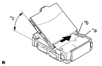
Contact the main body ECU guide against the housing side wall.
| *a | Housing Side Wall |
| *b | Guide |
| *c | 20° or more |
- HINT:
- The angle between the junction block and the main body ECU guide should be 20° or more.
MAIN BODY ECU > INSTALLATION |
| 1. INSTALL MAIN BODY ECU |
|
Contact the main body ECU guide against the housing side wall.
| *a | Housing Side Wall |
| *b | Guide |
| *c | 20° or more |
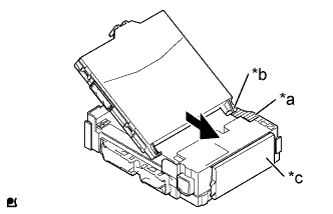 |
While aligning the guide with the housing side wall, slide the main body ECU toward the fuse area of the instrument panel junction block.
| *a | Housing Side Wall |
| *b | Guide |
| *c | Fuse Area |
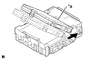 |
Slide the main body ECU until it contacts the A surface.
| *a | A surface |
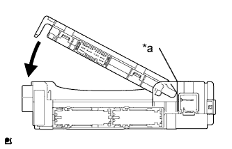 |
Rotate the main body ECU while holding it against the junction block A surface (axis of rotation).
| *a | A surface |
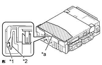 |
Rotate the main body ECU until it engages with the lock to install it.
| *1 | Main Body ECU |
| *2 | Instrument Panel Junction Block |
| *a | Push Area |
| 2. INSTALL JUNCTION BLOCK BRACKET |
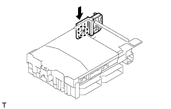 |
Engage the claw and install the junction block bracket.
| 3. INSTALL JUNCTION BLOCK BRACKET |
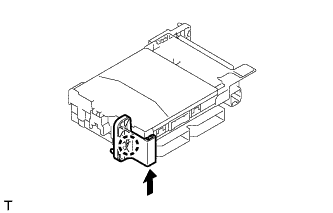 |
Engage the claw and install the junction block bracket.
| 4. INSTALL INSTRUMENT PANEL JUNCTION BLOCK ASSEMBLY |
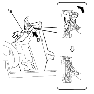 |
Connect the back side connector B indicated as shown in the illustration.
Slide the lever by the arrow indicated as shown in the illustration.
| *a | Lever |
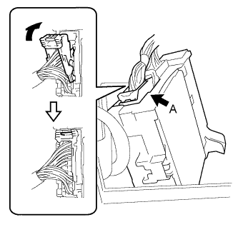 |
Connect the back side connector A indicated as shown in the illustration.
Engage the claw, 2 clamps and install the instrument panel junction block.
Tighten the 2 bolts.
Connect the main body ECU connector.
Connect the connectors to front side of the instrument panel junction block.
Engage the clamps.
| 5. INSTALL INSTRUMENT PANEL WIRE |
Engage the clamp and install the instrument panel wire.
Tighten the screw.
| 6. INSTALL LOWER NO. 2 INSTRUMENT PANEL FINISH PANEL (for LHD) |
Engage the 2 claws and 5 clips and install the instrument panel finish panel.
| 7. INSTALL UPPER INSTRUMENT PANEL SUB-ASSEMBLY (for LHD) |
| 8. INSTALL GLOVE COMPARTMENT DOOR ASSEMBLY (for RHD) |
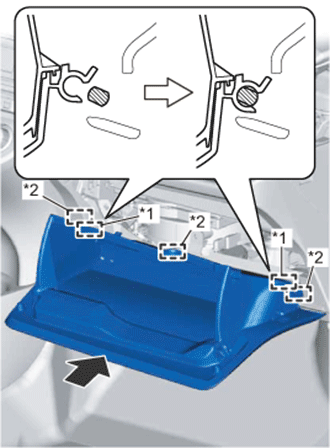 |
Engage the 3 guides and 2 hinges in the horizontal direction to install the glove compartment door.
| *1 | Hinge |
| *2 | Guide |
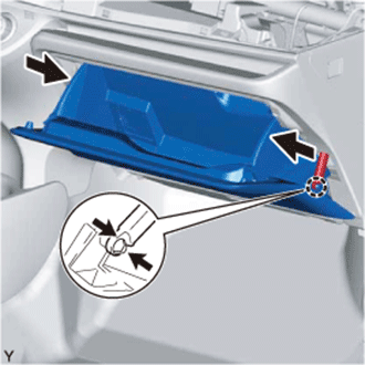 |
While pushing in the sides of the glove compartment door as indicated by the arrows in the illustration, close the door to engage it to the 2 stoppers.
Engage the claw and connect the glove compartment door stopper.