 |
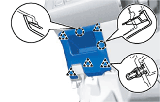
Disengage the 5 clips and the 2 claws and remove the instrument panel finish panel.
MAIN BODY ECU > REMOVAL |
| 1. REMOVE UPPER INSTRUMENT PANEL SUB-ASSEMBLY (for LHD) |
| 2. REMOVE LOWER NO. 2 INSTRUMENT PANEL FINISH PANEL (for LHD) |
|
Disengage the 5 clips and the 2 claws and remove the instrument panel finish panel.
| 3. REMOVE GLOVE COMPARTMENT DOOR ASSEMBLY (for RHD) |
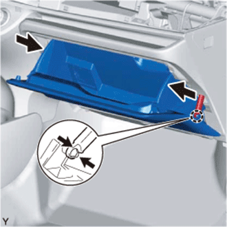 |
Disengage the claw and separate the glove compartment door stoppers from the glove compartment door.
Slightly flex the upper part of the glove compartment door to release the 2 stoppers and open the glove compartment door until it is horizontal.
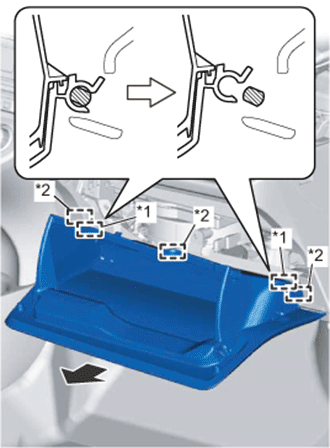 |
Pull the glove compartment door out horizontally to disengage the 2 hinges and 3 guides and remove the glove compartment door.
| *1 | Hinge |
| *2 | Guide |
| 4. SEPARATE INSTRUMENT PANEL WIRE |
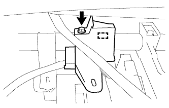 |
Remove the screw.
Disengage the clamp and remove the instrument panel wire.
| 5. REMOVE INSTRUMENT PANEL JUNCTION BLOCK ASSEMBLY |
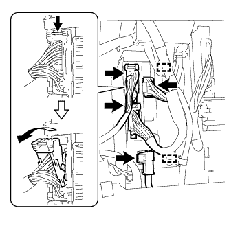 |
Disengage the clamps.
Disconnect the connectors on the front side of the instrument panel junction block.
Disconnect the main body ECU connector.
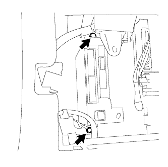 |
Remove the 2 bolts.
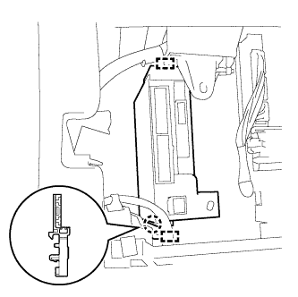 |
Disengage the claw and 2 clamps and separate the instrument panel junction block.
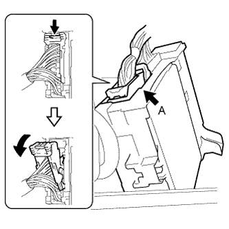 |
Disconnect the back side connector A indicated as shown in the illustration.
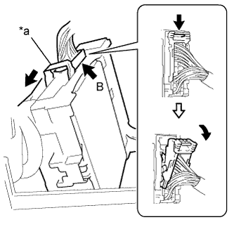 |
Slide the lever to the upward.
| *a | Lever |
Disconnect the back side connector B indicated as shown in the illustration.
Remove the instrument panel junction block.
| 6. REMOVE JUNCTION BLOCK BRACKET |
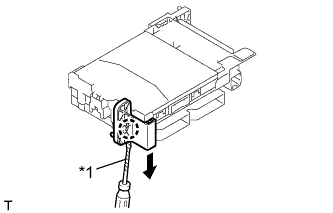 |
Using a screwdriver with its tip wrapped in protective tape, disengage the claw and remove the junction block bracket.
| *1 | Protective Tape |
| 7. REMOVE JUNCTION BLOCK BRACKET |
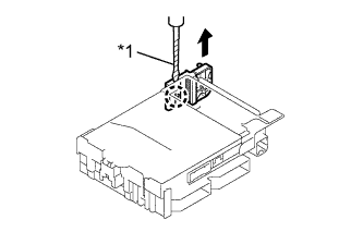 |
Using a screwdriver with its tip wrapped in protective tape, disengage the claw and remove the junction block bracket.
| *1 | Protective Tape |
| 8. REMOVE MAIN BODY ECU |
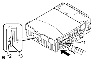 |
Release the lock on the junction block side.
| *1 | Protective Tape |
| *2 | Main Body ECU |
| *3 | Instrument Panel Junction Block |
While pressing the lock on the junction block side, insert a screwdriver with its tip wrapped in protective tape between the main body ECU and the junction block.
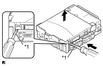 |
Do not pry the inserted screwdriver. Lift up the main body ECU to the point where the lock releases.
| *1 | Protective Tape |
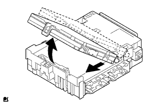 |
Remove the main body ECU by pulling it out from the junction block.