TURBOCHARGER
DESCRIPTION
CAUTION: The turbocharger is a performance part and must not be tampered with. The actuator bracket is an integral part of the turbocharger. Tampering with the actuator or other components can reduce durability by increasing cylinder pressure and thermal loading due to incorrect inlet and exhaust manifold pressure. Poor fuel economy and failure to meet regulatory emissions laws may result. Increasing the turbocharger boost WILL NOT increase engine power.
The turbocharger used on this vehicle is of the variable turbine type. These turbochargers use the entire exhaust energy to boost efficiency of the turbocharger and the engine.
The advantages of a turbocharger with variable turbine geometry are:
- Higher charge pressure already in the lower and in upper engine speed ranges.
- Higher torque as a result of improved cylinder charge.
- Reduction in exhaust emissions as a result of an improvement in the air supply of the engine.
- Increased power output as a result of the higher charge pressure combined with a reduced exhaust back pressure and thus improved charge cycle.
OPERATION
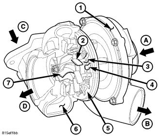
The exhaust gases of the engine are directed through the exhaust manifold into the turbine housing (6) onto the turbine wheel (7) . The flow energy of the exhaust gases cause the turbine wheel (7) to rotate. Consequently, the compressor wheel, which is connected through the turbine shaft with the turbine wheel (7), is driven at the same speed. The fresh air (A) inducted by the compressor wheel is compressed and passed to the engine .
The charge pressure is controlled by varying the position of the guide vanes (2). The guide stud (3) of the control linkage of the boost pressure actuator turns the adjusting ring (5) in the turbine housing (6). As a result, all the guide vanes (3) whose guide studs (4) likewise mesh into the adjusting ring (5), are also turned .
At low speeds, the flow cross-section is reduced by closing the guide vanes (2). Consequently the speed at which the exhaust gas impacts on the turbine wheel (7) is increased, as a result of which the speed of the turbocharger and thus the charge pressure rises.
At high engine speeds the guide vanes (2) are increasingly opened and the flow cross-section is thus enlarged, as a result of which the speed of the turbocharger reduces and the charge pressure drops.
REMOVAL - TURBOCHARGER
WARNING: THE NORMAL OPERATING TEMPERATURE OF THE EXHAUST SYSTEM IS VERY HIGH. NEVER WORK AROUND OR ATTEMPT TO SERVICE ANY PART OF THE EXHAUST SYSTEM UNTIL IT IS COOL. CARE SHOULD BE TAKEN WHEN WORKING NEAR THE TURBOCHARGER. THE TEMPERATURE OF THE TURBOCHARGER RISES TO A HIGH LEVEL AFTER A SHORT PERIOD OF ENGINE OPERATION TIME.
NOTE: THERE IS NO PROCEDURE FOR REPAIRING THE TURBOCHARGER. IF DAMAGE IS FOUND DURING INSPECTION, THE TURBOCHARGER MUST BE REPLACED.
1. Disconnect negative battery cable.
2. Remove the engine trim cover.
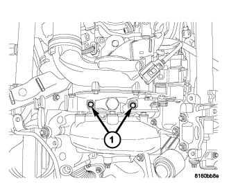
3. Remove air intake tube (air cleaner to turbo) (1).
4. Remove engine cover front bracket (2).
5. Remove air tube (turbo to cooler) (3).
6. Remove the turbo heat shield (4).
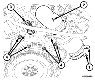
7. Remove the elbow to converter exhaust clamp (1).
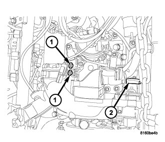
8. Remove the turbo front bracket retaining bolts (1).
9. Raise vehicle, remove front splash shield.
10. Drain cooling system (Refer to 7 - COOLING/ENGINE/COOLANT - STANDARD PROCEDURE).
11. Disconnect the downstream catalytic converter at the extension pipe.
12. Disconnect the extension pipe to muffler.
13. Disconnect O2 sensor wire connector.
14. Reposition extension pipe and catalytic converter.
15. Lower vehicle and disconnect catalytic converter to downstream catalytic converter clamp.
16. Remove upstream catalytic converter.
17. Disconnect transmission fill tube and trim cover bracket and set aside.
18. Disconnect exhaust elbow at turbo (2).
19. Disconnect EGR tube at manifold to left cylinder head (3).
20. Remove left and right exhaust manifold retaining bolts and gaskets (4).
21. Remove front turbo retaining bolts (1).
22. Remove turbo mount retaining bolts.
23. Remove turbo.
24. Disconnect turbo boost pressure servo connector (2).
INSTALLATION
1. Reconnect turbo boost pressure servo connector (2).
2. Position and install the turbocharger on the exhaust manifold, tighten the retainers to 30 N.m (22 lbs.ft.).
CAUTION: Make sure the gasket is installed properly or the turbo oil feed hole will be blocked.
3. Install front turbo retaining bolts and gasket and install turbo (1).
4. Install left and right exhaust manifold retaining bolts and gaskets (4).
5. Reconnect EGR tube at manifold to left cylinder head (3).
6. Reconnect EGR tube at manifold to left cylinder head (3).
7. Reconnect transmission fill tube and trim cover bracket and set aside.
8. Install upstream catalytic converter.
9. Raise vehicle and reconnect catalytic converter to downstream catalytic converter clamp.
10. Install extension pipe and catalytic converter.
11. Reconnect O2 sensor wire connector.
12. Reconnect the extension pipe to muffler.
13. Reconnect the downstream catalytic converter at the extension pipe.
14. Refill cooling system (Refer to 7 - COOLING/ENGINE/COOLANT - STANDARD PROCEDURE).
15. Install front splash shield.
16. Lower vehicle, install the turbo front bracket retaining bolts (2).
17. Install the exhaust clamp (elbow to converter) (1).
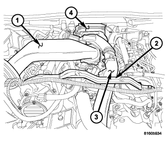
18. Install the turbo heat shield (4).
19. Install air tube (turbo to cooler) (3).
20. Install engine cover front bracket (2).
21. Install air intake tube (air cleaner to turbo) (1).
22. Install the engine trim cover.
23. Reconnect negative battery cable.