P1776-SOLENOID SWITCH VALVE LATCHED IN LR POSITION

For a complete wiring diagram Refer to Section 8W.
Theory of Operation
The Solenoid Switch Valve (SSV) controls the direction of the transmission fluid when the L/R Solenoid is energized. The SSV will be in the downshifted position in 1st gear, thus directing the fluid to the L/R clutch circuit. In 2nd through 5th gears, it will be in the upshifted position and directing the fluid into the torque converter clutch (TCC).
When in 2nd, 2nd Prime, 3rd, 4th, or 5th gear, the Torque Converter Clutch (TCC) can be engaged when certain conditions are met. The TCC piston is electronically modulated by increasing the duty cycle of the L/R solenoid until the torque converter slip difference (difference between engine and transmission input speed) is within 60 RPM. Then the L/R solenoid is fully energized (FEMCC / 100% duty cycle). Torque converter slip is monitored in FEMCC to ensure adequate clutch capacity.
- When Monitored:
Continuously when performing partial or full EMCC - PEMCC or FEMCC.
- Set Condition:
If the transmission senses the L/R pressure switch closing while performing PEMCC or FEMCC. This DTC will set after two unsuccessful attempts to perform PEMCC or FEMCC. This DTC can take up to five minutes of problem identification before illuminating the MIL.
| Possible Causes |
| RELATED DTC P0841 PRESENT |
| L/R PRESSURE SWITCH SENSE CIRCUIT OPEN |
| L/R PRESSURE SWITCH SENSE CIRCUIT SHORT TO GROUND |
| SOLENOID SWITCH VALVE |
| POWERTRAIN CONTROL MODULE |
| INTERMITTENT WIRING AND CONNECTORS |
Always perform the 45RFE/545RFE Pre-Diagnostic Troubleshooting Procedure before proceeding. (Refer to 21 - TRANSMISSION/TRANSAXLE/AUTOMATIC - 45RFE/545RFE - STANDARD PROCEDURE)
Diagnostic Test
1. DETERMINING IF RELATED DTC'S ARE PRESENTWith the scan tool, check for other transmission DTC's
Is the DTC P0841 present also?
Yes
- Refer to the Transmission category and perform the appropriate symptom.
No
- Go To 2
2. CHECK TO SEE IF DTC P1776 IS CURRENT
With the scan tool, Check the STARTS SINCE SET counter.
NOTE: NOTE: This counter only applies to the last DTC set.
Is the STARTS SINCE SET counter 2 or less?
Yes
- Go To 3
No
- Go To 7
3. PCM AND WIRING
Turn the ignition off to the lock position.
Remove the Starter Relay.
CAUTION: Removal of the Starter Relay will prevent the vehicle from being started in gear.
WARNING: The Starter Relay must be removed from the PDC. Failure to do so can result in personal injury or death.
NOTE: Failure to remove the Starter Relay can cause a Transmission - No Response condition.
Install the Transmission Simulator, Miller tool #8333.
Ignition on, engine not running.
With the Transmission Simulator, turn the Pressure Switch selector switch to the L/R position.
With the scan tool, monitor the L/R Pressure Switch state while pressing the Pressure Switch Test button on the Transmission Simulator.
Did the state of the L/R Pressure Switch change while pressing the Pressure Switch Test button?
Yes
- Go To 4
No
- Go To 5
4. SOLENOID SWITCH VALVE
Remove the Valve Body per the Service Information.
Inspect the Solenoid Switch Valve and plugs for sticking in the bore and/or wear.
Were there any problems found?
Yes
- Clean and repair as necessary per the Service Information.
- Perform 45RFE/545RFE TRANSMISSION VERIFICATION TEST. (Refer to 21 - TRANSMISSION/TRANSAXLE/AUTOMATIC - 45RFE/545RFE - STANDARD PROCEDURE)
No
- Go To 7
5. L/R PRESSURE SWITCH SENSE CIRCUIT OPEN
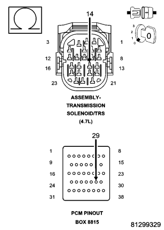
Turn the ignition off to the lock position.
Disconnect the Transmission Simulator, Miller tool #8333.
Disconnect the PCM C4 harness connector and connect Miller tool #8815.
NOTE: Note: Check connectors - Clean/repair as necessary.
CAUTION: Do not probe the PCM harness connectors. Probing the PCM harness connectors will damage the PCM terminals resulting in poor terminal to pin connection. Install Miller tool #8815 to perform diagnosis.
Measure the resistance of the (T50) L/R Pressure Switch Sense circuit between the appropriate terminal of Miller tool #8815 to the Solenoid/TRS Assembly harness connector.
Is the resistance above 5.0 ohms?
Yes
- Repair the (T50) L/R Pressure Switch Sense circuit for an open.
- Perform 45RFE/545RFE TRANSMISSION VERIFICATION TEST. (Refer to 21 - TRANSMISSION/TRANSAXLE/AUTOMATIC - 45RFE/545RFE - STANDARD PROCEDURE)
No
- Go To 6
6. (T50) L/R PRESSURE SWITCH SENSE CIRCUIT SHORT TO GROUND
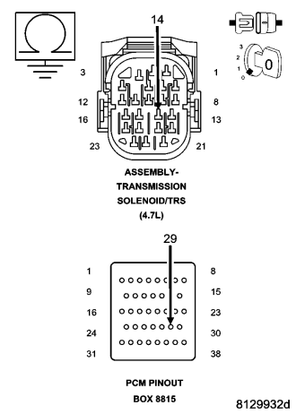
Measure the resistance between ground and the (T50) L/R Pressure Switch Sense circuit.
Is the resistance below 5.0 ohms?
Yes
- Repair the (T50) L/R Pressure Switch Sense circuit for a short to ground.
- Perform 45RFE/545RFE TRANSMISSION VERIFICATION TEST. (Refer to 21 - TRANSMISSION/TRANSAXLE/AUTOMATIC - 45RFE/545RFE - STANDARD PROCEDURE)
No
- Using the schematics as a guide, check the Powertrain Control Module (PCM) terminals for corrosion, damage, or terminal push out. Pay particular attention to all power and ground circuits. If no problems are found, replace the PCM per the Service Information. With the scan tool, perform QUICK LEARN.
- Perform 45RFE/545RFE TRANSMISSION VERIFICATION TEST. (Refer to 21 - TRANSMISSION/TRANSAXLE/AUTOMATIC - 45RFE/545RFE - STANDARD PROCEDURE)
7. INTERMITTENT WIRING AND CONNECTORS
The conditions necessary to set this DTC are not present at this time.
Using the schematics as a guide, inspect the wiring and connectors specific to this circuit.
Wiggle the wires while checking for shorted and open circuits.
This DTC can also be set by the Solenoid Switch Valve intermittently sticking in it's bore under extreme temperature conditions, or by a worn Solenoid Switch Valve or plugs.
With the scan tool, check the DTC EVENT DATA to help identify the conditions in which the DTC was set.
Where there any problems found?
Yes
- Repair as necessary.
- Perform 45RFE/545RFE TRANSMISSION VERIFICATION TEST. (Refer to 21 - TRANSMISSION/TRANSAXLE/AUTOMATIC - 45RFE/545RFE - STANDARD PROCEDURE)
No
- Test Complete.