ASSEMBLY-TRANSMISSION SOLENOID/TRS
DESCRIPTION
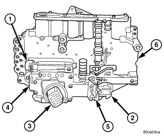
The transmission solenoid/TRS assembly is internal to the transmission and mounted on the valve body assembly . The assembly consists of six solenoids that control hydraulic pressure to the six friction elements (transmission clutches), and the torque converter clutch. The pressure control solenoid is located on the side of the solenoid/TRS assembly. The solenoid/TRS assembly also contains the Transmission Range Sensor (TRS) and five pressure switches that feed information to the TCM.
OPERATION
SOLENOIDS
Solenoids are used to control the L/R, 2C, 4C, OD, and UD friction elements. The reverse clutch is controlled by line pressure and the position of the manual valve in the valve body. All the solenoids are contained within the Solenoid and Pressure Switch Assembly. The solenoid and pressure switch assembly contains one additional solenoid, Multi-Select (MS), which serves primarily to provide 2nd and 3rd gear limp-in operation.
The solenoids receive electrical power from the Transmission Control Relay through a single wire. The TCM energizes or operates the solenoids individually by grounding the return wire of the solenoid as necessary. When a solenoid is energized, the solenoid valve shifts, and a fluid passage is opened or closed (vented or applied), depending on its default operating state. The result is an apply or release of a frictional element.
The MS and UD solenoids are normally applied to allow transmission limp-in in the event of an electrical failure.
The continuity of the solenoids and circuits are periodically tested. Each solenoid is turned on or off depending on its current state. An inductive spike should be detected by the TCM during this test. If no spike is detected, the circuit is tested again to verify the failure. In addition to the periodic testing, the solenoid circuits are tested if a speed ratio or pressure switch error occurs.
PRESSURE SWITCHES
The TCM relies on five pressure switches to monitor fluid pressure in the L/R, 2C, 4C, UD, and OD hydraulic circuits. The primary purpose of these switches is to help the TCM detect when clutch circuit hydraulic failures occur. The switches close at approximately 23 psi and open at approximately 11 psi, and simply indicate whether or not pressure exists. The switches are continuously monitored by the TCM for the correct states (open or closed) in each gear as shown in the following chart:
| GEAR |
L/R |
2C |
4C |
UD |
OD |
| R |
OP |
OP |
OP |
OP |
OP |
| P/N |
CL |
OP |
OP |
OP |
OP |
| 1ST |
CL* |
OP |
OP |
CL |
OP |
| 2ND |
OP |
CL |
OP |
CL |
OP |
| 2ND PRIME (ERS 3RD) |
OP |
OP |
CL |
CL |
OP |
| 3RD (ERS 4TH) |
OP |
OP |
OP |
CL |
CL |
| 4TH (ERS 5TH) |
OP |
OP |
CL |
OP |
CL |
| 5TH (ERS D) |
OP |
CL |
OP |
OP |
CL |
| *L/R is closed if output speed is below 100 rpm in Drive and Manual 2. L/R is open in Manual 1. |
|||||
A Diagnostic Trouble Code (DTC) will set if the TCM senses any switch open or closed at the wrong time in a given gear.
REMOVAL
NOTE: If the Transmission Solenoid/TRS Assembly is being replaced, the Quick Learn Procedure must be performed. (Refer to 8 - ELECTRICAL/ELECTRONIC CONTROL MODULES/TRANSMISSION CONTROL MODULE - STANDARD PROCEDURE)
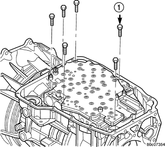
1. Remove the valve body from the transmission . (Refer to 21 - TRANSMISSION/AUTOMATIC - 45RFE/545RFE/VALVE BODY - REMOVAL)
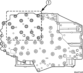
2. Remove the bolts (1) holding the transmission solenoid/TRS assembly onto the valve body .
3. Separate the transmission solenoid/TRS assembly from the valve body.
INSTALLATION
1. Place TRS selector plate in the PARK position.
2. Position the transmission solenoid/TRS assembly onto the valve body. Be sure that both alignment dowels are fully seated in the valve body and that the TRS switch contacts are properly positioned in the selector plate
3. Install the bolts (1) to hold the transmission solenoid/TRS assembly onto the valve body.
4. Tighten the solenoid assembly screws adjacent to the arrows cast into the bottom of the valve body first. Tighten the screws to 6 N·m (50 in.lbs.).
5. Tighten the remainder of the solenoid assembly screws to 6 N·m (50 in.lbs.).
6. Install the valve body into the transmission.