CONVERTER-TORQUE
DESCRIPTION
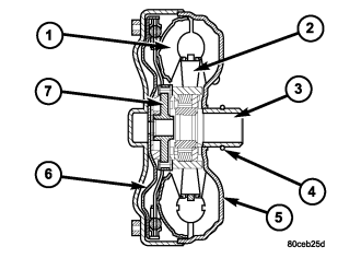
| 1 - TURBINE ASSEMBLY |
5 - IMPELLER ASSEMBLY |
| 2 - STATOR |
6 - CONVERTER CLUTCH PISTON |
| 3 - CONVERTER HUB |
7 - TURBINE HUB |
| 4 - O-RING |
The torque converter is a hydraulic device that couples the engine crankshaft to the transmission. The torque converter consists of an outer shell with an internal turbine (1), a stator (2), an overrunning clutch, an impeller (5), and an electronically applied converter clutch (6). The converter clutch provides reduced engine speed and greater fuel economy when engaged. Clutch engagement also provides reduced transmission fluid temperatures. The torque converter hub (3) drives the transmission oil (fluid) pump and contains an o-ring seal (4) to better control oil flow.
The torque converter is a sealed, welded unit that is not repairable and is serviced as an assembly.
CAUTION: The torque converter must be replaced if a transmission failure resulted in large amounts of metal or fiber contamination in the fluid.
IMPELLER
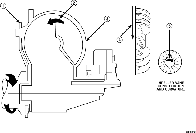
| Impeller |
| 1 - ENGINE FLEXPLATE |
4 - ENGINE ROTATION |
| 2 - OIL FLOW FROM IMPELLER SECTION INTO TURBINE SECTION |
5 - ENGINE ROTATION |
| 3 - IMPELLER VANES AND COVER ARE INTEGRAL |
The impeller is an integral part of the converter housing. The impeller consists of curved blades placed radially along the inside of the housing on the transmission side of the converter. As the converter housing is rotated by the engine, so is the impeller, because they are one and the same and are the driving members of the system.
TURBINE
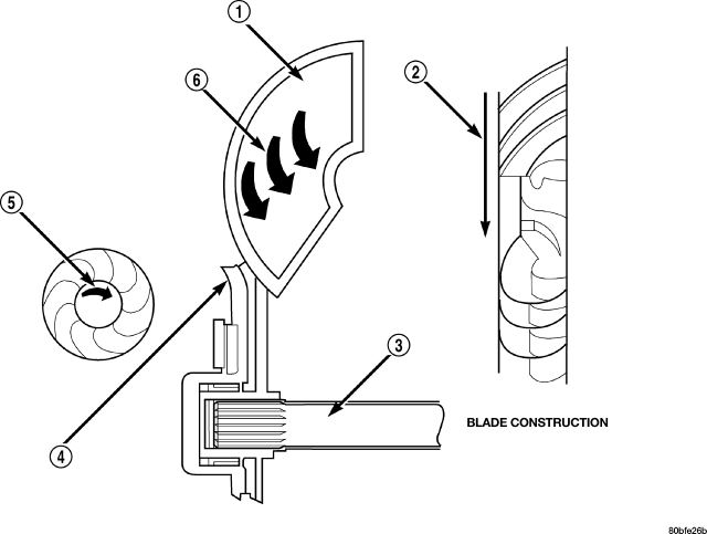
| Turbine |
| 1 - TURBINE VANE |
4 - PORTION OF TORQUE CONVERTER COVER |
| 2 - ENGINE ROTATION |
5 - ENGINE
ROTATION |
| 3 - INPUT SHAFT |
6 - OIL FLOW WITHIN TURBINE SECTION |
The turbine is the output, or driven, member of the converter. The turbine is mounted within the housing opposite the impeller, but is not attached to the housing. The input shaft is inserted through the center of the impeller and splined into the turbine. The design of the turbine is similar to the impeller, except the blades of the turbine are curved in the opposite direction.
STATOR
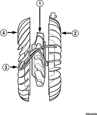
The stator assembly is mounted on a stationary shaft which is an integral part of the oil pump. The stator (1) is located between the impeller (2) and the turbine (4) within the torque converter case.
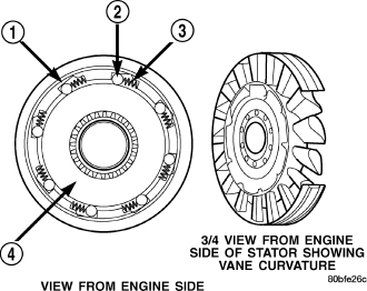
The stator contains an over-running clutch (1-4), which allows the stator to rotate only in a clockwise direction. When the stator is locked against the over-running clutch, the torque multiplication feature of the torque converter is operational.
TORQUE CONVERTER CLUTCH (TCC)
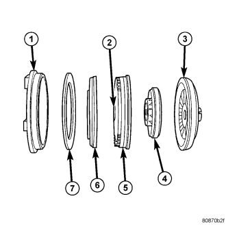
The TCC was installed to improve the efficiency of the torque converter that is lost to the slippage of the fluid coupling. Although the fluid coupling provides smooth, shock-free power transfer, it is natural for all fluid couplings to slip. If the impeller (3) and turbine (5) were mechanically locked together, a zero slippage condition could be obtained. A hydraulic piston (6) with friction material (7) was added to the turbine assembly (5) to provide this mechanical lock-up.
In order to reduce heat build-up in the transmission and buffer the powertrain against torsional vibrations, the TCM can duty cycle the L/R-CC Solenoid to achieve a smooth application of the torque converter clutch. This function, referred to as Electronically Modulated Converter Clutch (EMCC) can occur at various times depending on the following variables:
- Shift lever position
- Current gear range
- Transmission fluid temperature
- Engine coolant temperature
- Input speed
- Throttle angle
- Engine speed
OPERATION
The converter impeller (driving member), which is integral to the converter housing and bolted to the engine drive plate, rotates at engine speed. The converter turbine (driven member), which reacts from fluid pressure generated by the impeller, rotates and turns the transmission input shaft.
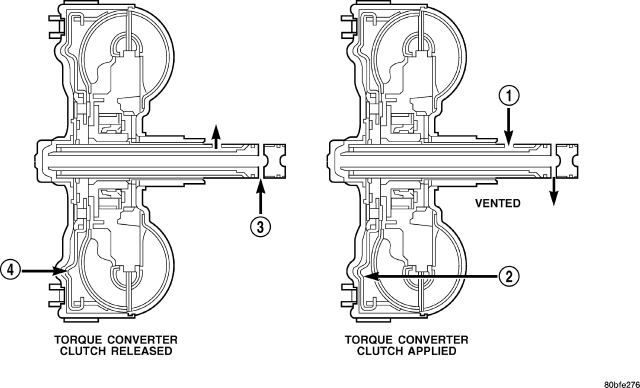
| Torque Converter Fluid Operation - Typical |
| 1 - APPLY PRESSURE |
3 - RELEASE PRESSURE |
| 2 - THE PISTON MOVES SLIGHTLY FORWARD |
4 - THE PISTON MOVES SLIGHTLY REARWARD |
TURBINE
As the fluid that was put into motion by the impeller blades strikes the blades of the turbine, some of the energy and rotational force is transferred into the turbine and the input shaft. This causes both of them (turbine and input shaft) to rotate in a clockwise direction following the impeller. As the fluid is leaving the trailing edges of the turbine's blades it continues in a “hindering” direction back toward the impeller. If the fluid is not redirected before it strikes the impeller, it will strike the impeller in such a direction that it would tend to slow it down.
STATOR
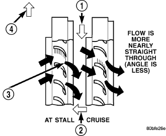
Torque multiplication is achieved by locking the stator's over-running clutch to its shaft . Under stall conditions (the turbine is stationary), the oil leaving the turbine blades strikes the face of the stator blades and tries to rotate them in a counterclockwise direction. When this happens the over-running clutch of the stator locks and holds the stator from rotating. With the stator locked, the oil strikes the stator blades and is redirected into a “helping” direction before it enters the impeller. This circulation of oil from impeller to turbine, turbine to stator, and stator to impeller, can produce a maximum torque multiplication of about 2.4:1. As the turbine begins to match the speed of the impeller, the fluid that was hitting the stator in such as way as to cause it to lock-up is no longer doing so. In this condition of operation, the stator begins to free wheel and the converter acts as a fluid coupling.
TORQUE CONVERTER CLUTCH (TCC)
In a standard torque converter, the impeller and turbine are rotating at about the same speed and the stator is freewheeling, providing no torque multiplication. By applying the turbine's piston and friction material to the front cover, a total converter engagement can be obtained. The result of this engagement is a direct 1:1 mechanical link between the engine and the transmission.
The clutch can be engaged in second, third, fourth, and fifth gear ranges depending on overdrive control switch position. If the overdrive control switch is in the normal ON position, the clutch will engage after the shift to fourth gear, and above approximately 72 km/h (45 mph). If the control switch is in the OFF position, the clutch will engage after the shift to third gear, at approximately 56 km/h (35 mph) at light throttle.
The TCM controls the torque converter by way of internal logic software. The programming of the software provides the TCM with control over the L/R-CC Solenoid. There are four output logic states that can be applied as follows:
- No EMCC
- Partial EMCC
- Full EMCC
- Gradual-to-no EMCC
NO EMCC
Under No EMCC conditions, the L/R Solenoid is OFF. There are several conditions that can result in NO EMCC operations. No EMCC can be initiated due to a fault in the transmission or because the TCM does not see the need for EMCC under current driving conditions.
PARTIAL EMCC
Partial EMCC operation modulates the L/R Solenoid (duty cycle) to obtain partial torque converter clutch application. Partial EMCC operation is maintained until Full EMCC is called for and actuated. During Partial EMCC some slip does occur. Partial EMCC will usually occur at low speeds, low load and light throttle situations.
FULL EMCC
During Full EMCC operation, the TCM increases the L/R Solenoid duty cycle to full ON after Partial EMCC control brings the engine speed within the desired slip range of transmission input speed relative to engine rpm.
GRADUAL-TO-NO EMCC
This operation is to soften the change from Full or Partial EMCC to No EMCC. This is done at mid-throttle by decreasing the L/R Solenoid duty cycle.
REMOVAL
1. Remove transmission and torque converter from vehicle. (Refer to 21 - TRANSMISSION/AUTOMATIC - 45RFE/545RFE - REMOVAL)
2. Place a suitable drain pan under the converter housing end of the transmission.
CAUTION: Verify that transmission is secure on the lifting device or work surface, the center of gravity of the transmission will shift when the torque converter is removed creating an unstable condition. The torque converter is a heavy unit. Use caution when separating the torque converter from the transmission.
3. Pull the torque converter forward until the center hub clears the oil pump seal.
4. Separate the torque converter from the transmission.
INSTALLATION
NOTE: Check converter hub and drive flats for sharp edges, burrs, scratches, or nicks. Polish the hub and flats with 320/400 grit paper or crocus cloth if necessary. Verify that the converter hub o-ring is properly installed and is free from debris. The hub must be smooth to avoid damaging the pump seal at installation.
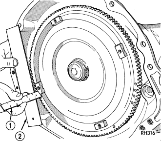
1. Lubricate oil pump seal lip with transmission fluid.
2. Place torque converter in position on transmission.
CAUTION: Do not damage oil pump seal or converter hub o-ring while inserting torque converter into the front of the transmission.
3. Align torque converter to oil pump seal opening.
4. Insert torque converter hub into oil pump.
5. While pushing torque converter inward, rotate converter until converter is fully seated in the oil pump gears.
6. Check converter seating with a scale (1) and straightedge (2). Surface of converter lugs should be at least 13 mm (1/2 in.) to rear of straightedge when converter is fully seated.
7. If necessary, temporarily secure converter with C-clamp attached to the converter housing.
8. Install the transmission in the vehicle.
9. Fill the transmission with the recommended fluid.