GEARTRAIN-PLANETARY
DESCRIPTION
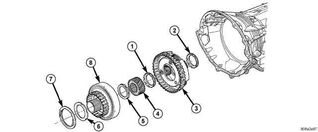
| Reaction Planetary Geartrain |
| 1 - THRUST BEARING NUMBER 8 |
5 - THRUST BEARING NUMBER 7 |
| 2 - THRUST BEARING NUMBER 9 |
6 - THRUST PLATE (SELECT) |
| 3 - REACTION PLANETARY CARRIER |
7 - THRUST BEARING NUMBER 6 |
| 4 - REACTION SUN GEAR |
8 - REACTION ANNULUS |
The planetary geartrain is located behind the 4C retainer/bulkhead, toward the rear of the transmission. The planetary geartrain consists of three primary assemblies:
- Reaction (3, 4, 8).
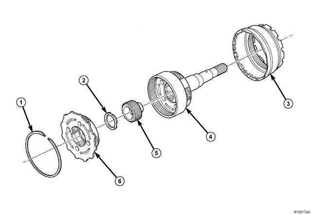
- Reverse (6).
- Input (3,4, 5).
OPERATION
REACTION PLANETARY GEARSET
The reaction planetary carrier and reverse sun gear of the reaction planetary gearset are a single component which is held by the 2C clutch when required. The reaction annulus gear is a stand alone component that can be driven by the reverse clutch or held by the 4C clutch. The reaction sun gear is driven by the overdrive clutch.
REVERSE PLANETARY GEARSET
The reverse planetary gearset is the middle of the three planetary sets. The reverse planetary carrier can be driven by the overdrive clutch as required. The reverse planetary carrier is also splined to the input annulus gear, which can be held by the low/reverse clutch. The reverse planetary annulus, input planetary carrier, and output shaft are all one piece.
INPUT PLANETARY GEARSET
The input sun gear of the input planetary gearset is driven by the underdrive clutch.
DISASSEMBLY
1. Remove the snap-ring (1) holding the input annulus (3) into the input carrier (4).
2. Remove the input annulus (3) from the input carrier (4).
3. Remove the reverse planetary gear carrier (6).
4. Remove the number 10 thrust bearing (2) from the input sun gear (5).
5. Remove the input sun gear (5) from the input carrier (4).
CLEANING
Clean the planetary components in solvent and dry them with compressed air.
INSPECTION
Inspect each planetary carrier assembly for damage. Check that each pinion gear rotates freely and smoothly on its shaft. Check that the tabbed thrust washer on each side of each pinion gear is in place. Check that the outer ends of the pinion shafts are not discolored from overheating. Replace the carrier assembly if jammed or sticky pinion gears, spun or missing tabbed washers, or blackened pinion shafts are found.
Check sun gear and driving shell condition. Replace the gear if damaged or if the bushings are scored or worn. The bushings are not serviceable. Replace the driving shell if worn, cracked or damaged.
Replace planetary gear sets if gears, pinion pins, or carrier are damaged in any way. Replace the annulus gears and supports if either component is worn or damaged.
Replace the output shaft if the machined surfaces are scored, pitted, or damaged in any way. Also replace the shaft if the splines are damaged, or exhibits cracks at any location.
ASSEMBLY
NOTE: Clean and inspect all components. Replace any components which show evidence of excessive wear or scoring.
1. Install the input sun gear (6) into the input carrier (5).
2. Install the number 10 thrust bearing (2) onto the rear of the reverse planetary carrier (7) with the inner race toward the carrier.
3. Install the number 9 thrust bearing onto the front of the reverse planetary carrier (7) with the outer race toward the carrier and the inner race facing upward.
4. Install the reverse planetary gear carrier (7) into the input carrier (5).
5. Install the input annulus gear (4) into the input carrier (5).
6. Install the snap-ring (1) to hold the input annulus gear (4) into the input carrier (5).