P0643-SENSOR REFERENCE VOLTAGE 1 CIRCUIT HIGH
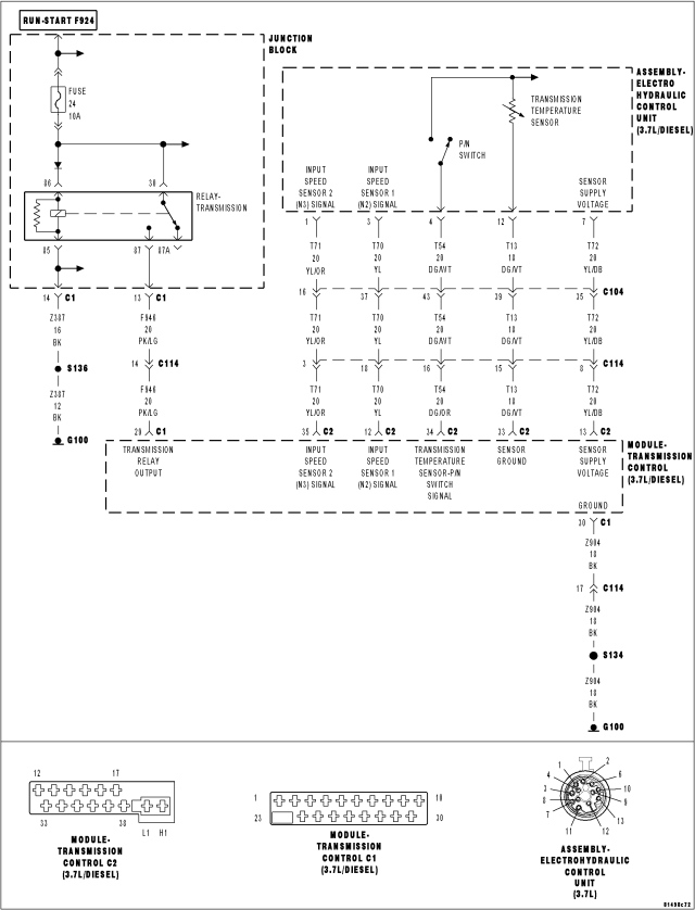
For a complete wiring diagram Refer to Section 8W
Theory of Operation
The Sensor Supply Voltage circuit supplies a 6 volt power supply for the two input speed sensors. The Sensor Supply Voltage circuit is constantly monitored for correct voltage between 4.8 to 7.2 volts. If the voltage does not stay within the 4.8 to 7.2 volt range, the appropriate DTC will set.
- When Monitored:
Continuously with the ignition on and no overvoltage condition exist.
- Set Condition:
When the monitored sensor voltage is not within specified limits and rises above 7.2 volts.
| Possible Causes |
| (T72) SENSOR SUPPLY VOLTAGE CIRCUIT SHORT TO VOLTAGE |
| (T72) SENSOR SUPPLY VOLTAGE CIRCUIT SHORT TO OTHER CIRCUITS |
| TRANSMISSION CONTROL MODULE |
Always perform the Pre-Diagnostic Troubleshooting procedure before proceeding. (Refer to 21 - TRANSMISSION/TRANSAXLE/AUTOMATIC - NAG1 - STANDARD PROCEDURE)
Diagnostic Test
1. CHECK FOR SPEED SENSOR DTCSWith the scan tool, check for other transmission DTCs.
Are there any speed sensor and/or temperature sensor DTCs present?
Yes
- Refer to the AUTOMATIC TRANSMISSION NAG1 - ELECTRICAL DIAGNOSTICS category and perform the appropriate symptom.
No
- Go To 2
2. CHECK SOLENOID SUPPLY VOLTAGE ON THE SCAN TOOL
Start the engine.
With the scan tool, check the Transmission Solenoid Supply Voltage.
Is the Transmission Solenoid Supply Voltage above 7.2 volts?
Yes
- Go To 3
No
- Go To 5
3. CHECK (T72) SENSOR SUPPLY CIRCUIT VOLTAGE
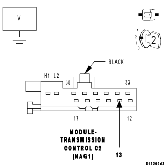
While back probing, measure the voltage of the (T72) Solenoid Supply Voltage circuit in the TCM harness connector.
Does the measured voltage match the voltage reading on the scan tool ± 0.2 volts?
Yes
- Go To 4
No
- Using the schematics as a guide, check the Transmission Control Module (TCM) terminals for corrosion, damage, or terminal push out. Pay particular attention to all power and ground circuits. If no problems are found, replace the TCM per the Service Information. Refer to 8 - ELECTRICAL/ELECTRONIC CONTROL MODULES/TRANSMISSION CONTROL MODULE for the appropriate service procedures.
- Perform NAG1 TRANSMISSION VERIFICATION TEST. (Refer to 21 - TRANSMISSION/TRANSAXLE/AUTOMATIC - NAG1 - STANDARD PROCEDURE)
4. (T72) SENSOR SUPPLY VOLTAGE CIRCUIT SHORT TO ANOTHER CIRCUIT
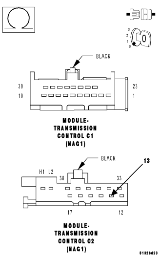
Turn the ignition off to the lock position.
Disconnect the Transmission Electrohydraulic Control Unit Assembly harness connector.
Disconnect all TCM harness connectors.
Measure the resistance between the (T72) Solenoid Supply Voltage circuit and all other circuits in the Transmission Electrohydraulic Control Unit harness connector.
Is the resistance below 5.0 ohms between the (T72) Solenoid Supply Voltage circuit and all other circuits in the Transmission Electrohydraulic Control Unit Assembly harness connector?
Yes
- Repair the (T72) Solenoid Supply Voltage circuit for a short to another circuit(s).
- Perform NAG1 TRANSMISSION VERIFICATION TEST. (Refer to 21 - TRANSMISSION/TRANSAXLE/AUTOMATIC - NAG1 - STANDARD PROCEDURE)
No
- Using the schematics as a guide, check the Transmission Control Module (TCM) terminals for corrosion, damage, or terminal push out. Pay particular attention to all power and ground circuits. If no problems are found, replace the TCM per the Service Information. Refer to 8 - ELECTRICAL/ELECTRONIC CONTROL MODULES/TRANSMISSION CONTROL MODULE for the appropriate service procedures.
- Perform NAG1 TRANSMISSION VERIFICATION TEST. (Refer to 21 - TRANSMISSION/TRANSAXLE/AUTOMATIC - NAG1 - STANDARD PROCEDURE)
5. INTERMITTENT WIRING AND CONNECTORS
The conditions necessary to set this DTC are not present at this time.
Using the schematics as a guide, inspect the wiring and connectors specific to this circuit.
Wiggle the wires while checking for shorted and open circuits.
Were there any problems found?
Yes
- Repair as necessary.
- Perform NAG1 TRANSMISSION VERIFICATION TEST. (Refer to 21 - TRANSMISSION/TRANSAXLE/AUTOMATIC - NAG1 - STANDARD PROCEDURE)
No
- Test Complete.