DIAGNOSIS AND TESTING
- P0562-BATTERY VOLTAGE LOW - ESM
- P0563-BATTERY VOLTAGE HIGH - ESM
- P0607-ECU INTERNAL PERFORMANCE - ESM
- P0930-BTSI CONTROL CIRCUIT LOW - ESM
- P0931-BTSI CONTROL CIRCUIT HIGH - ESM
- P2775-AUTOSTICK UPSHIFT SWITCH CIRCUIT PERFORMANCE - ESM
- P2779-AUTOSTICK DOWNSHIFT SWITCH CIRCUIT PERFORMANCE - ESM
- U0002-CAN C BUS OFF PERFORMANCE - ESM
- U0100-LOST COMMUNICATION WITH ECM/PCM - ESM
- U0121-LOST COMMUNICATION WITH ANTI-LOCK BRAKE MODULE - ESM
- U0141-LOST COMMUNICATION WITH FRONT CONTROL MODULE - ESM
P0562-BATTERY VOLTAGE LOW - ESM
For a complete wiring diagramRefer to Section 8W
Theory of Operation
The Shift Lever Assembly monitors ignition voltage. The DTC will set if the monitored battery voltage drops below 6.0 volts and a temporary limp in will be activated. If the voltage rises above 9.0 volts, normal operations is resumed.
- When Monitored:
Continuously with the ignition on.
- Set Condition:
When monitored battery voltage drops below 6.0 volts.
| Possible Causes |
| VEHICLE CHARGING SYSTEM |
| (F1) IGNITION UNLOCK RUN START CIRCUIT |
| (Z911) GROUND CIRCUIT |
| SHIFT LEVER ASSEMBLY |
Always perform the Pre-Diagnostic Troubleshooting procedure before proceeding. (Refer to 21 - TRANSMISSION/TRANSAXLE/AUTOMATIC - NAG1 - STANDARD PROCEDURE)
Diagnostic Test
1. CHECK FOR ENGINE CHARGING SYSTEM DTCSWith the scan tool, read Engine DTCs.
Are there any Engine Charging System DTCs present?
Yes
- Refer to the 9 - ENGINE ELECTRICAL DIAGNOSTICS and perform the appropriate symptom.
No
- Go To 2
2. CHECK (F1) IGNITION UNLOCK RUN START CIRCUIT
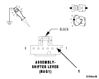
Turn the ignition off to the lock position.
Disconnect the Shift Lever Assembly harness connector.
Turn the ignition on.
Using a 12-volt test light connected to ground, check the (F1) Ignition Unlock Run Start circuit in the Shift Lever Assembly harness connector.
NOTE: The test light must illuminate brightly. Compare the brightness to that of a direct connection to the battery.
Does the test light illuminate brightly?
Yes
- Go To 3
No
- Repair the (F1) Ignition Unlock Run Start circuit for high resistance.
- Perform NAG1 TRANSMISSION VERIFICATION TEST - VER 1. (Refer to 21 - TRANSMISSION/TRANSAXLE/AUTOMATIC - NAG1 - STANDARD PROCEDURE)
3. CHECK (Z911) GROUND CIRCUIT
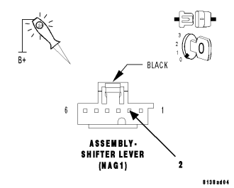
Turn the ignition off to the lock position.
Using a 12-volt test light connected to 12-volts, check the (Z911) Ground circuit in the Shift Lever Assembly harness connector.
NOTE: The test light must illuminate brightly. Compare the brightness to that of a direct connection to the battery.
Does the test light illuminate brightly?
Yes
- Go To4
- Perform NAG1 TRANSMISSION VERIFICATION TEST - VER 1. (Refer to 21 - TRANSMISSION/TRANSAXLE/AUTOMATIC - NAG1 - STANDARD PROCEDURE)
No
- Repair the (Z911) Ground circuit for high resistance.
- Perform NAG1 TRANSMISSION VERIFICATION TEST - VER 1. (Refer to 21 - TRANSMISSION/TRANSAXLE/AUTOMATIC - NAG1 - STANDARD PROCEDURE)
4. SHIFT LEVER ASSEMBLY
Reconnect all disconnected harness connectors.
With the scan tool, erase Shift Lever DTC's.
Start the engine and raise the engine speed to 2000 RPM.
With the scan tool, read Shift Lever DTC's.
Did the P0562-BATTERY VOLTAGE LOW DTC reset?
Yes
- Replace the Shift Lever Assembly per the Service Information
- Perform NAG1 TRANSMISSION VERIFICATION TEST - VER 1. (Refer to 21 - TRANSMISSION/TRANSAXLE/AUTOMATIC - NAG1 - STANDARD PROCEDURE)
No
- Test Complete.
P0563-BATTERY VOLTAGE HIGH - ESM
For a complete wiring diagram Refer to Section 8W
- When Monitored:
Continuously with the ignition on.
- Set Condition:
When the monitored battery voltage rises above 16.0 volts.
| Possible Causes |
| CHARGING SYSTEM DTCS |
| VEHICLE WAS JUMP STARTED INCORRECTLY |
| SHIFT LEVER ASSEMBLY |
Always perform the NAG1 Pre-Diagnostic Troubleshooting procedure before proceeding. (Refer to 21 - TRANSMISSION/TRANSAXLE/AUTOMATIC - NAG1 - STANDARD PROCEDURE)
Theory of Operation
The Shift Lever Assembly monitors ignition voltage. The DTC will set, if the monitored battery voltage rises above 16.0 volts.
Diagnostic Test
1. CHECK FOR CHARGING SYSTEM DTCSWith the scan tool, read Engine DTCs.
NOTE: This includes any one trip faults.
Are there any Engine Charging System DTCs present?
Yes
- Refer to the 9 - ENGINE ELECTRICAL DIAGNOSTICS and perform the appropriate symptom.
- Perform NAG1 TRANSMISSION VERIFICATION TEST. (Refer to 21 - TRANSMISSION/TRANSAXLE/AUTOMATIC - NAG1 - STANDARD PROCEDURE)
No
- Go To 2
2. VEHICLE WAS JUMP STARTED INCORRECTLY
Verify if the vehicle was jump started by another vehicle using a 24-volt charging system or incorrectly jump started with the 12 volt battery in series.
Was the vehicle jump started by another vehicle?
Yes
- This is the cause of the DTC. Erase the DTC and return the vehicle to the customer.
- Perform NAG1 TRANSMISSION VERIFICATION TEST. (Refer to 21 - TRANSMISSION/TRANSAXLE/AUTOMATIC - NAG1 - STANDARD PROCEDURE)
No
- Go To 3
3. SHIFT LEVER ASSEMBLY
Reconnect all disconnected harness connectors.
With the scan tool, erase Shift Lever DTC's.
Start the engine and raise the engine speed to 2000 RPM.
With the scan tool, read Shift Lever DTC's.
Did the P0563-BATTERY VOLTAGE HIGH DTC reset?
Yes
- Replace the Shift Lever Assembly per the Service Information
- Perform NAG1 TRANSMISSION VERIFICATION TEST. (Refer to 21 - TRANSMISSION/TRANSAXLE/AUTOMATIC - NAG1 - STANDARD PROCEDURE)
No
- Test Complete.
P0607-ECU INTERNAL PERFORMANCE - ESM
For a complete wiring diagram Refer to Section 8W
- When Monitored:
Continuously with the ignition on.
- Set Condition:
If the Shift Lever Assembly controller detects an error with the optical sensors or internal checksum value is not correct.
| Possible Causes |
| SHIFTER LEVER ASSEMBLY |
Always perform the NAG1 Pre-Diagnostic Troubleshooting procedure before proceeding. (Refer to 21 - TRANSMISSION/TRANSAXLE/AUTOMATIC - NAG1 - STANDARD PROCEDURE)
Theory of Operation
The Shifter Lever Assembly (SLA) Electronic Shift Module (ESM) performs various internal tests to verify proper controller operation. This DTC indicates that there is an issue with the Shifter's internal processor.
Diagnostic Test
1. SHIFTER LEVER ASSEMBLYView repair
Repair
- Using the schematics as a guide, check the Shifter Lever Assembly Control Module terminals for corrosion, damage, or terminal push out. Pay particular attention to all power and ground circuits. If no problems are found, replace the Shifter Lever Assembly per the Service Information. (Refer to 21 - TRANSMISSION/TRANSAXLE/AUTOMATIC - NAG1/SHIFT MECHANISM - REMOVAL)
- Perform NAG1 TRANSMISSION VERIFICATION TEST. (Refer to 21 - TRANSMISSION/TRANSAXLE/AUTOMATIC - NAG1 - STANDARD PROCEDURE)
P0930-BTSI CONTROL CIRCUIT LOW - ESM
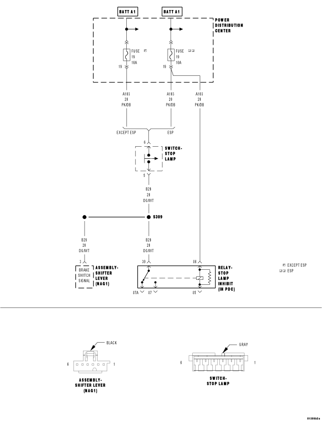
For a complete wiring diagram Refer to Section 8W
- When Monitored:
Continuously with the ignition on.
- Set Condition:
The DTC will set if the high side driver detects a short to ground for 10 seconds.
| Possible Causes |
| ENGINE BRAKE DTCS PRESENT |
| ABS DTCS PRESENT |
| (B29) BRAKE SWITCH SIGNAL SHORT TO GROUND |
| SHIFTER LEVER ASSEMBLY |
Always perform the NAG1 Pre-Diagnostic Troubleshooting procedure before proceeding. (Refer to 21 - TRANSMISSION/TRANSAXLE/AUTOMATIC - NAG1 - STANDARD PROCEDURE)
Theory of Operation
The brake switch signal must be active before the shift lever can be moved out of the park position. The Shifter Lever Assembly (SLA) Electronic Shift Module (ESM) receives two brake switch signals. The first signal is a CAN C Bus message sent to the shifter lever assembly. The second signal is a hard wired brake switch signal to the shifter lever assembly. The CAN C Bus message is the primary brake switch signal and the hard wired signal serves as the backup brake switch signal.
Diagnostic Test
1. ENGINE DTCS PRESENTWith the scan tool, read Engine DTCs.
Are there any Engine brake DTCs present?
Yes
- Refer to 9 - ENGINE ELECTRICAL DIAGNOSTICS and perform the appropriate diagnostic procedure.
- Perform NAG1 TRANSMISSION VERIFICATION TEST. (Refer to 21 - TRANSMISSION/TRANSAXLE/AUTOMATIC - NAG1 - STANDARD PROCEDURE)
No
- Go To 2
2. ABS MODULE DTCS PRESENT
With the scan tool, read ABS Module DTCs.
Are there any ABS DTCs present?
Yes
- Refer to Section 5 - BRAKES - ABS ELECTRICAL DIAGNOSTICS and perform the appropriate diagnostic procedure.
- Perform NAG1 TRANSMISSION VERIFICATION TEST. (Refer to 21 - TRANSMISSION/TRANSAXLE/AUTOMATIC - NAG1 - STANDARD PROCEDURE)
No
- Go To 3
3. (B29) BRAKE SWITCH SIGNAL SHORT TO GROUND
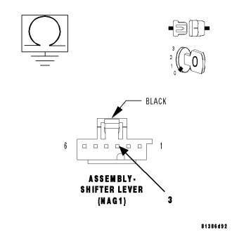
Turn the ignition off to the lock position.
Disconnect the Shifter Lever Assembly harness connector.
NOTE: Check connectors - Clean/repair as necessary.
Measure the resistance between ground and the (B29) Brake Switch Signal circuit.
Is the resistance below 5.0 ohms?
Yes
- Repair the (B29) Brake Switch Signal for a short to ground.
- Perform NAG1 TRANSMISSION VERIFICATION TEST. (Refer to 21 - TRANSMISSION/TRANSAXLE/AUTOMATIC - NAG1 - STANDARD PROCEDURE)
No
- Go To 4
4. SHIFTER LEVER ASSEMBLY
Using the schematics as a guide, inspect the wiring and connectors. Repair as necessary. Pay particular attention to all power and ground circuits.
If there are no possible causes remaining, view repair.
Repair
- Replace the Shifter Lever Assembly per the Service Information. (Refer to 21 - TRANSMISSION/TRANSAXLE/AUTOMATIC - NAG1/SHIFT MECHANISM - REMOVAL)
- Perform NAG1 TRANSMISSION VERIFICATION TEST. (Refer to 21 - TRANSMISSION/TRANSAXLE/AUTOMATIC - NAG1 - STANDARD PROCEDURE)
P0931-BTSI CONTROL CIRCUIT HIGH - ESM
For a complete wiring diagram Refer to Section 8W
- When Monitored:
Continuously with the ignition key on.
- Set Condition:
The DTC will set if the high side driver detects an open load for 10 seconds.
| Possible Causes |
| ENGINE BRAKE DTC'S PRESENT |
| ABS DTC'S PRESENT |
| (B29) BRAKE SWITCH SIGNAL OPEN |
| (B29) BRAKE SWITCH SIGNAL SHORT TO VOLTAGE |
| SHIFTER LEVER ASSEMBLY |
Always perform the NAG1 Pre-Diagnostic Troubleshooting procedure before proceeding. (Refer to 21 - TRANSMISSION/TRANSAXLE/AUTOMATIC - NAG1 - STANDARD PROCEDURE)
Theory of Operation
The brake switch signal must be active before the shift lever can be moved out of the park position. The Shifter Lever Assembly (SLA) Electronic Shift Module (ESM) receives two brake switch signals. The first signal is a CAN C Bus message sent to the shifter lever assembly. The second signal is a hard wired brake switch signal to the shifter lever assembly. The CAN C Bus message is the primary brake switch signal and the hard wired signal serves as the backup brake switch signal. These two brake switch signals are compared against each other to verify proper brake switch operation.
Diagnostic Test
1. ENGINE DTCs PRESENTWith the scan tool, read Engine DTCs.
Are there any Engine brake DTCs present?
Yes
- Refer to 9 — ENGINE ELECTRICAL DIAGNOSTICS and perform the appropriate diagnostic procedure.
- Perform NAG1 TRANSMISSION VERIFICATION TEST. (Refer to 21 - TRANSMISSION/TRANSAXLE/AUTOMATIC - NAG1 - STANDARD PROCEDURE)
No
- Go To 2
2. ABS MODULE DTCs PRESENT
With the scan tool, read ABS Module DTCs.
Are there any ABS DTCs present?
Yes
- Refer to Section 5 - BRAKES - ABS ELECTRICAL DIAGNOSTICS and perform the appropriate diagnostic procedure.
- Perform NAG1 TRANSMISSION VERIFICATION TEST. (Refer to 21 - TRANSMISSION/TRANSAXLE/AUTOMATIC - NAG1 - STANDARD PROCEDURE)
No
- Go To 3
3. (B29) BRAKE SWITCH SIGNAL OPEN
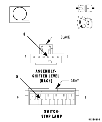
Turn the ignition off to the lock position.
Disconnect the Shifter Lever Assembly harness connector.
Disconnect the Stop Lamp Switch harness connector.
NOTE: Check connectors - Clean/repair as necessary.
Measure the resistance of the (B29) Brake Switch Signal circuit between the Shifter Lever Assembly harness connector and the Stop Lamp Switch.
Is the resistance above 5.0 ohms?
Yes
- Repair the (B29) Brake Switch Signal for an open.
- Perform NAG1 TRANSMISSION VERIFICATION TEST. (Refer to 21 - TRANSMISSION/TRANSAXLE/AUTOMATIC - NAG1 - STANDARD PROCEDURE)
No
- Go To 4
4. (B29) BRAKE SWITCH SIGNAL SHORT TO VOLTAGE
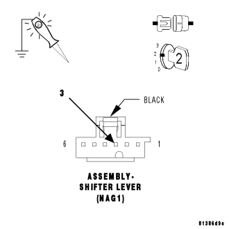
Turn the ignition off to the lock position.
Disconnect the Shifter Lever Assembly harness connector.
NOTE: Check connectors - Clean/repair as necessary.
Turn the ignition on.
Measure the voltage of the (B29) Brake Switch Signal circuit.
Is the voltage above 0.5 volts?
Yes
- Repair the (B29) Brake Switch Signal for a short to voltage.
- Perform NAG1 TRANSMISSION VERIFICATION TEST. (Refer to 21 - TRANSMISSION/TRANSAXLE/AUTOMATIC - NAG1 - STANDARD PROCEDURE)
No
- Replace the Shifter Lever Assembly per the Service Information. (Refer to 21 - TRANSMISSION/TRANSAXLE/AUTOMATIC - NAG1/SHIFT MECHANISM - REMOVAL)
- Perform NAG1 TRANSMISSION VERIFICATION TEST. (Refer to 21 - TRANSMISSION/TRANSAXLE/AUTOMATIC - NAG1 - STANDARD PROCEDURE)
P2775-AUTOSTICK UPSHIFT SWITCH CIRCUIT PERFORMANCE - ESM
For a complete wiring diagram Refer to Section 8W
- When Monitored:
When in AutoStick mode.
- Set Condition:
When the expected switch state is not correctly sensed by the Shifter Lever Assembly. If the upshift switch signal is detected as active in gear position other than drive or both upshift and downshift signals are active at the same time.
| Possible Causes |
| SHIFTER LEVER ASSEMBLY |
Always perform the NAG1 Pre-Diagnostic Troubleshooting procedure before proceeding. (Refer to 21 - TRANSMISSION/TRANSAXLE/AUTOMATIC - NAG1 - STANDARD PROCEDURE)
Theory of Operation
The AutoStick Switch is integrated into the Shifter Lever Assembly. The gear requested by the AutoStick selection in then sent over the CAN C bus to the TCM to engage the requested gear.
1. SHIFTER LEVER ASSEMBLY
View repair
Repair
- Using the schematics as a guide, check the Shifter Lever Assembly (SLA) Electronic Shift Module (ESM) terminals for corrosion, damage, or terminal push out. Pay particular attention to all power and ground circuits. If no problems are found, replace the Shifter Lever Assembly per the Service Information. Refer to Shift Mechanism for the appropriate service procedures. (Refer to 21 - TRANSMISSION/TRANSAXLE/AUTOMATIC - NAG1/SHIFT MECHANISM - REMOVAL)
- Perform NAG1 TRANSMISSION VERIFICATION TEST. (Refer to 21 - TRANSMISSION/TRANSAXLE/AUTOMATIC - NAG1 - STANDARD PROCEDURE)
P2779-AUTOSTICK DOWNSHIFT SWITCH CIRCUIT PERFORMANCE - ESM
For a complete wiring diagram Refer to Section 8W
- When Monitored:
When in AutoStick mode.
- Set Condition:
When the expected switch state is not correctly sensed by the Shifter Lever Assembly (SLA) Electronic Shift Module (ESM). If the upshift switch signal is detected as active in gear position other than drive or both upshift and downshift signals are active at the same time.
| Possible Causes |
| SHIFTER LEVER ASSEMBLY |
Always perform the NAG1 Pre-Diagnostic Troubleshooting procedure before proceeding. (Refer to 21 - TRANSMISSION/TRANSAXLE/AUTOMATIC - NAG1 - STANDARD PROCEDURE)
Theory of Operation
The AutoStick Switch is integrated into the Shift Lever Assembly. The gear requested by the AutoStick selection is then sent over the CAN C bus from the Electronic Shift Module (ESM) to the TCM to engage the requested gear.
Diagnostic Test
1. SHIFT LEVER ASSEMBLYView repair
Repair
- Using the schematics as a guide, check the Shifter Lever Assembly (SLA) Electronic Shift Module (ESM) terminals for corrosion, damage, or terminal push out. Pay particular attention to all power and ground circuits. If no problems are found, replace the Shifter Lever Assembly per the Service Information. (Refer to 21 - TRANSMISSION/TRANSAXLE/AUTOMATIC - NAG1/SHIFT MECHANISM - REMOVAL)
- Perform NAG1 TRANSMISSION VERIFICATION TEST. (Refer to 21 - TRANSMISSION/TRANSAXLE/AUTOMATIC - NAG1 - STANDARD PROCEDURE)
U0002-CAN C BUS OFF PERFORMANCE - ESM
For a complete wiring diagramRefer to Section 8W
Theory of Operation
Some controllers communicate with other controllers over the CAN C bus. The Shift Lever Assembly (SLA) contains a Electronic Shift Module (ESM) that continuously monitors the bus activity and receives the messages it needs. The CAN C bus is also used to communicate transmission MIL status to the Engine Controller.
Refer to 8-ELECTRICAL/ELECTRONIC CONTROL MODULES - DIAGNOSIS AND TESTING for diagnostic procedures and for further possible causes.
U0100-LOST COMMUNICATION WITH ECM/PCM - ESM
For a complete wiring diagramRefer to Section 8W
Theory of Operation
Some controllers communicate with other controllers over the CAN C bus. The Shift Lever Assembly (SLA) contains a Electronic Shift Module (ESM) that continuously monitors the bus activity and receives the messages it needs. The CAN C bus is also used to communicate transmission MIL status to the Engine Controller.
Refer to 8-ELECTRICAL/ELECTRONIC CONTROL MODULES - DIAGNOSIS AND TESTING for diagnostic procedures and for further possible causes.
U0121-LOST COMMUNICATION WITH ANTI-LOCK BRAKE MODULE - ESM
For a complete wiring diagramRefer to Section 8W
Theory of Operation
Some controllers communicate with other controllers over the CAN C bus. The Shift Lever Assembly (SLA) contains a Electronic Shift Module (ESM) that continuously monitors the bus activity and receives the messages it needs. The CAN C bus is also used to communicate transmission MIL status to the Engine Controller.
Refer to 8-ELECTRICAL/ELECTRONIC CONTROL MODULES - DIAGNOSIS AND TESTING for diagnostic procedures and for further possible causes.
U0141-LOST COMMUNICATION WITH FRONT CONTROL MODULE - ESM
For a complete wiring diagramRefer to Section 8W
Theory of Operation
Some controllers communicate with other controllers over the CAN C bus. The Shift Lever Assembly (SLA) contains a Electronic Shift Module (ESM) that continuously monitors the bus activity and receives the messages it needs. The CAN C bus is also used to communicate transmission MIL status to the Engine Controller.
Refer to 8-ELECTRICAL/ELECTRONIC CONTROL MODULES - DIAGNOSIS AND TESTING for diagnostic procedures and for further possible causes.