BATTERY CABLES
DESCRIPTION
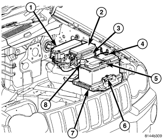
The battery cables (4) and (8) are large gauge, stranded copper wires sheathed within a heavy plastic or synthetic rubber insulating jacket. The wire used in the battery cables combines excellent flexibility and reliability with high electrical current carrying capacity. The battery cables feature a stamped brass clamping type female battery terminal crimped onto one end of the battery cable wire and then solder-dipped. A square headed pinch-bolt and hex nut are installed at the open end of the female battery terminal clamp. Large eyelet type terminals are crimped onto the opposite end of the battery cable wire and then solder-dipped. The battery positive cable wires (8) have a red insulating jacket to provide visual identification and feature a larger female battery terminal clamp to allow connection to the larger battery positive terminal post. The battery negative cable wires (4) have a black insulating jacket and a smaller female battery terminal clamp.
The battery cables cannot be repaired and, if damaged or faulty they must be replaced. Both the battery positive and negative cables are available for service replacement only as a unit with the battery wire harness, which may include portions of the wiring circuits for the generator and other components on some models. Refer to the appropriate wiring information for the location of the proper battery cable wire harness diagrams. The wiring information also includes proper wire and connector repair procedures, further details on wire harness routing and retention, as well as pin-out and location views for the various wire harness connectors, splices and grounds.
OPERATION
The battery cables connect the battery terminal posts to the vehicle electrical system. These cables also provide a return path for electrical current generated by the charging system for restoring the voltage potential of the battery. The female battery terminal clamps on the ends of the battery cable wires provide a strong and reliable connection of the battery cable to the battery terminal posts. The terminal pinch bolts allow the female terminal clamps to be tightened around the male terminal posts on the top of the battery. The eyelet terminals secured to the ends of the battery cable wires opposite the female battery terminal clamps provide secure and reliable connection of the battery to the vehicle electrical system.
REMOVAL
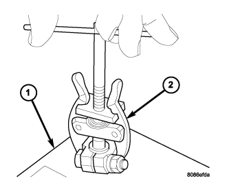
NOTE: It may be necessary to use a battery terminal puller (2) if the battery cable terminal clamps are seized on to the battery posts.
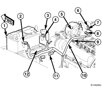
Both the battery negative cable (2) and the battery positive cable (4) are serviced in the battery wire harness (10). If either battery cable is damaged or faulty, the battery wire harness assembly must be replaced.
1. Turn the ignition switch to the Off position. Be certain that all electrical accessories are turned off.
2. Disconnect the battery negative cable terminal clamp (2) from the battery negative terminal post. If necessary, use a battery terminal puller to remove the terminal clamp from the battery post.
3. Lift the battery positive cable terminal clamp cover (3) to gain access to the pinch-bolt hex nut.
4. Disconnect the battery positive cable terminal clamp (4) from the battery positive terminal post. If necessary, use a battery terminal puller to remove the terminal clamp from the battery post.
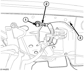
5. Remove the screw (1) that secures the battery negative cable eyelet terminal (2) to the inner fender (3).
6. Unlatch and open the cover on the Power Distribution Center (PDC)(1) and Integrated Power Module (IPM)(2).
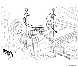
7. Remove the two nuts that secure the battery positive cable eyelet terminal to the B(+) terminal studs in the PDC.
8. Remove the nut that secures the battery positive cable eyelet terminal to the B(+) terminal stud in the IPM.
9. Remove both battery positive cable eyelet terminals from the B(+) terminal studs in the PDC and IPM.
10. Disconnect the battery wire harness three pin connector (11).
11. Remove the battery wire harness three pin connector (11) from the battery tray (12).
12. On 3.7L and 4.7L engines remove the nut (6) that secures the generator output cable eyelet terminal (7) to the generator output terminal stud.
13. Remove the generator output cable eyelet terminal from the generator output terminal stud.
14. Disconnect the battery wire harness connector (8) from the generator field terminal connector receptacle on the back of the generator.
15. Remove the battery wire harness retaining clip (9) from the valve cover stud.
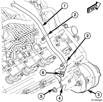
16. On 5.7L engines remove the nut (5) that secures the generator output cable eyelet terminal (4) to the generator output terminal stud.
17. Remove the generator output cable eyelet terminal from the generator output terminal stud.
18. Disconnect the battery wire harness connector (6) from the generator field terminal connector receptacle on the back of the generator (3).
19. Remove the battery wire harness retaining clips (2) from the valve cover studs.
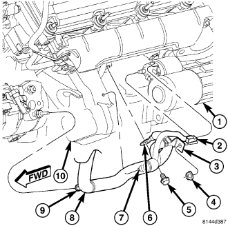
20. Raise the vehicle on a hoist, (Refer to LUBRICATION & MAINTENANCE/LIFT POINTS - STANDARD PROCEDURE).
21. Remove the bolt (5) that secures the battery negative cable ground eyelet terminal (6) to the engine block (10).
22. Remove the nut (4) that secures the battery positive cable eyelet terminal (3) to the B(+) terminal stud on the starter solenoid.
23. Remove the battery positive cable eyelet terminal from the B(+) terminal stud on the starter solenoid.
24. Disconnect the battery wire harness connector (2) from the connector receptacle on the starter solenoid.
25. Remove the battery wire harness retaining clips (7) & (9) from the engine.
26. Remove the battery wire harness from the engine compartment.
INSTALLATION
NOTE: Both the battery negative cable and the battery positive cable are serviced in the battery wire harness. If either battery cable is damaged or inoperative, the battery wire harness assembly must be replaced.
1. Clean and inspect the battery cable terminal clamps and the battery terminal posts, (Refer to 8 - ELECTRICAL/BATTERY SYSTEM - CLEANING).
2. Position the battery wire harness assembly (10) into the vehicle.
3. Raise the vehicle on a hoist, (Refer to LUBRICATION & MAINTENANCE/LIFT POINTS - STANDARD PROCEDURE).
4. Install the battery wire harness retaining clips (7) & (9) to the engine.
5. Reconnect the battery wire harness connector (2) to the connector receptacle on the starter solenoid.
6. Install the battery positive cable eyelet terminal (3) onto the B(+) terminal stud on the starter solenoid.
7. Install and tighten the nut (4) that secures the battery positive cable eyelet terminal (3) to the B(+) terminal stud on the starter solenoid. Tighten the nut to 11 N·m (95 in. lbs.).
8. Install and tighten the bolt (5) that secures the battery negative cable ground eyelet terminal (6) to the engine block (10). Tighten the bolt to 11 N·m (95 in. lbs.).
9. Lower the vehicle.
10. Install the battery wire harness retaining clips (2) to the valve cover studs.
11. On 5.7L engines, reconnect the battery wire harness connector (6) to the generator field terminal connector receptacle on the back of the generator.
12. Install the generator output cable eyelet terminal (4) onto the generator output terminal stud.
13. Install and tighten the nut (5) that secures the generator output cable eyelet terminal (4) to the generator output terminal stud. Tighten the nut to 14 N·m (125 in. lbs.).
14. On 3.7L and 4.7L engines, reconnect the battery wire harness connector (8) to the generator field terminal connector receptacle on the back of the generator.
15. Install the generator output cable eyelet terminal (7) onto the generator output terminal stud.
16. Install and tighten the nut (6) that secures the generator output cable eyelet terminal (7) to the generator output terminal stud. Tighten the nut to 14 N·m (125 in. lbs.).
17. Install the battery wire harness retaining clip (9) onto the valve cover stud.
18. Install the battery wire harness three pin connector (11) onto the battery tray (12).
19. Connect the battery wire harness three pin connector (11).
20. Install both battery positive cable eyelet terminals onto the B(+) terminal studs in the Power Distribution Center (PDC) and Integrated Power Module (IPM).
21. Install and tighten the nuts that secure the battery positive cable eyelet terminals onto the B(+) terminal studs in the PDC and IPM. Tighten the nut to 11.5 N·m (105 in. lbs.).
22. Close and latch the covers on the PDC (1) and IPM (2).
23. Install and tighten the screw (1) that secures the battery negative cable eyelet terminal (2) to the inner fender (3). Tighten the screw to 28 N·m (20.5 ft. lbs.).
24. Reconnect the battery positive cable terminal clamp (4) to the battery positive terminal post. Tighten the terminal clamp pinch-bolt hex nut to 5.5 N·m (50 in. lbs.).
25. Secure the battery positive cable terminal clamp cover (3) over the battery positive cable terminal clamp (4).
26. Reconnect the battery negative cable terminal clamp (2) to the battery negative terminal post. Tighten the terminal clamp pinch-bolt hex nut to 5.5 N·m (50 in. lbs.).
27. Apply a thin coating of petroleum jelly or chassis grease to the exposed surfaces of the battery cable terminal clamps and the battery terminal posts.