SHOES
- DESCRIPTION
- OPERATION
- REMOVAL
- CLEANING - REAR DRUM IN HAT BRAKE
- INSPECTION - REAR DRUM IN HAT BRAKE
- INSTALLATION
DESCRIPTION
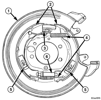
Drum in hat park brakes are dual shoe, internal expanding units with an automatic self adjusting mechanism .
OPERATION
When the parking brake pedal is pulled the brake cable pulls the brake shoes outward against the brake drum. When the brake pedal is released the return springs attached to the brake shoes pull the shoes back to there original position.
REMOVAL
1. Raise vehicle.
2. Remove rear wheel and tire assembly.
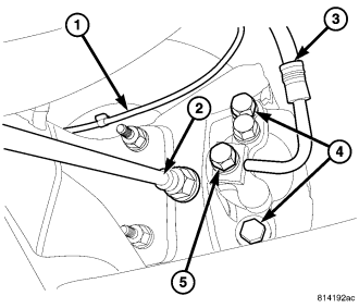
3. Remove the 2 caliper bolts (4) then remove the caliper Support the caliper, Do not let the caliper hang by the brake hose.
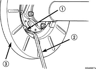
4. Remove rubber access plug (1) from back of rear disc brake support plate (3).
5. If necessary retract parking brake shoes with brake adjuster tool (2). Position tool at top of star wheel and rotate wheel.
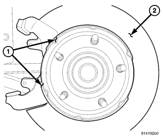
6. Remove rotor from axle hub flange.
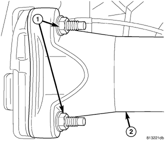
7. Remove the four axle flange nuts (1).
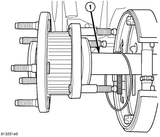
8. Remove the axle shaft (1) from the rear differential (Refer to 3 - DIFFERENTIAL & DRIVELINE/REAR AXLE - C213R/AXLE SHAFTS - REMOVAL).
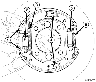
9. Remove the shoe to shoe return spring (6) with needle nose pliers & then remove the adjuster (5).
10. Remove the shoe to shoe return spring (3) with brake pliers.
11. Remove shoe hold-down clips (4) and pins. Clip is held in place by pin which fits in clip notch. To remove clip, first push clip ends together and slide clip until head of pin clears narrow part of notch. Then remove clip (4) and pin.
12. Remove shoes (1) off the actuator lever (2) for the park brake then remove the shoes (1).
CLEANING - REAR DRUM IN HAT BRAKE
Clean the individual brake components, including the support plate exterior, with a water dampened cloth or with brake cleaner. Do not use any other cleaning agents. Remove light rust and scale from the brake shoe contact pads on the support plate with fine sandpaper.
INSPECTION - REAR DRUM IN HAT BRAKE
As a general rule, riveted brake shoes should be replaced when worn to within 0.78 mm (1/32 in.) of the rivet heads. Bonded lining should be replaced when worn to a thickness of 1.6 mm (1/16 in.).
Examine the lining contact pattern to determine if the shoes are bent or the drum is tapered. The lining should exhibit contact across its entire width. Shoes exhibiting contact only on one side should be replaced and the drum checked for runout or taper .
Inspect the adjuster screw assembly. Replace the assembly if the star wheel or threads are damaged, or the components are severely rusted or corroded .
Discard the brake springs and retainer components if worn, distorted or collapsed. Also replace the springs if a brake drag condition had occurred. Overheating will distort and weaken the springs.
Inspect the brake shoe contact pads on the support plate, replace the support plate if any of the pads are worn or rusted through. Also replace the plate if it is bent or distorted .
INSTALLATION
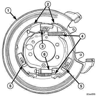
1. Install the park brake shoes (1) onto the actuator lever (2).
2. Install shoes on support plate with hold down clips and pins (4) . Be sure shoes are properly engaged in the park brake actuator lever (2).
3. Install the return spring (3).
4. Lubricate and install adjuster screw assembly (5). Be sure notched ends of screw assembly are properly seated on shoes and that star wheel is aligned with access hole in the support plate.
5. Install shoe to shoe adjuster spring (6). Needle nose pliers can be used to connect spring to each shoe.
6. Install the axle shaft (1) to the rear differential (Refer to 3 - DIFFERENTIAL & DRIVELINE/REAR AXLE - C213R/AXLE SHAFTS - INSTALLATION).
7. Install and tighten the axle flange nuts (1).
8. Install rotor to the axle hub.
9. Install the caliper and the 2 mounting bolts (4) to 44 N·m (32 ft. lbs.).
10. Adjust the parking brake shoes.
11. Install wheel and tire assembly.
12. Lower vehicle and verify correct parking brake operation.