RESISTOR-BLOWER MOTOR
DESCRIPTION
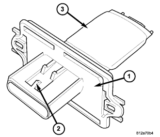
A blower motor resistor is used on vehicles equipped with the manual temperature control (MTC) heating-A/C system. Vehicles equipped with the automatic temperature control (ATC) heating-A/C system use a blower motor power module, instead of the blower motor resistor (refer to 24 - HEATING & AIR CONDITIONING/CONTROLS-FRONT/MODULE-POWER-BLOWER MOTOR - DESCRIPTION).
The blower motor resistor is mounted to the rear of the HVAC housing, directly behind the glove box. The blower motor resistor consists of a molded plastic mounting plate (1) with an integral wire connector receptacle (2). Concealed behind the mounting plate are coiled resistor wires contained within a ceramic heat sink (3).
The blower motor resistor is accessed for service by removing the glove box.
OPERATION
The blower motor resistor is connected to the vehicle electrical system through a dedicated wire lead and connector of the HVAC wire harness. The blower motor resistor has multiple resistor wires, each of which will reduce the current flow through the blower motor to change the blower motor speed.
The blower motor control in the MTC heating-A/C system directs the ground path for the blower motor through the correct resistor wire to obtain the selected speed. With the blower motor control in the lowest speed position, the ground path for the blower motor is applied through all of the resistor wires. Each higher speed selected with the blower motor control applies the blower motor ground path through fewer of the resistor wires, increasing the blower motor speed.
The blower motor resistor cannot be adjusted or repaired and must be replaced if found inoperative or damaged (such as a cracked ceramic heat sink).
REMOVAL
WARNING: Disable the airbag system before attempting any steering wheel, steering column, or instrument panel component diagnosis or service. Disconnect and isolate the negative battery (ground) cable, then wait two minutes for the airbag system capacitor to discharge before performing further diagnosis or service. This is the only sure way to disable the airbag system. Failure to take the proper precautions could result in accidental airbag deployment and possible personal injury or death.
WARNING: The blower motor resistor may get very hot during normal operation. If the blower motor was turned on prior to servicing the blower motor resistor, wait five minutes to allow the blower motor resistors to cool before performing diagnosis or service. Failure to take this precaution can result in possible personal injury.
CAUTION: Do not operate the blower motor with the blower motor resistor removed from the circuit. Failure to take this precaution can result in vehicle damage.
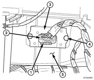
NOTE: LHD model shown. RHD model similar.
1. Disconnect and isolate the negative battery cable.
2. Remove the glove box from the instrument panel (refer to 23 - BODY/INSTRUMENT PANEL/GLOVE BOX - REMOVAL).
3. Disengage the wire harness connector locking tab (1) and disconnect the wire harness connector (2) from the blower motor resistor (3).
4. Remove the two screws (4) that secure the blower motor resistor to the HVAC housing (5).
5. Remove the blower motor resistor from the HVAC housing.
INSTALLATION
NOTE: LHD model shown. RHD model similar.
1. Position the blower motor resistor (3) into the HVAC housing (5).
2. Install the two screws (4) that secure the blower motor resistor to the HVAC housing. Tighten the screws to 2 N·m (17 in. lbs.).
3. Connect the wire harness connector (2) to the blower motor resistor and engage the wire harness connector locking tab (1).
4. Install the glove box into the instrument panel (refer to 23 - BODY/INSTRUMENT PANEL/GLOVE BOX - INSTALLATION).
5. Reconnect the negative battery cable.