SENSOR-EVAPORATOR TEMPERATURE
DESCRIPTION
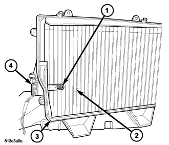
NOTE: LHD model shown. RHD model similar.
The evaporator temperature sensor (1) measures the temperature of the conditioned air downstream of the A/C evaporator (2). The evaporator temperature sensor is an electrical thermistor within a molded plastic case that is inserted into the HVAC housing (3) near the coldest point of the A/C evaporator. Two terminals within the connector receptacle (4) connect the sensor to the vehicle electrical system through a wire lead and connector of the HVAC wire harness.
The external location of the evaporator temperature sensor allows the sensor to be removed or installed without disturbing the refrigerant in the A/C system.
OPERATION
The evaporator temperature sensor monitors the temperature of the conditioned air downstream of the A/C evaporator and supplies an input signal to the A/C-heater control. The A/C-heater control uses the evaporator temperature sensor input signal to optimize A/C system performance and to protect the A/C system from evaporator freezing. The evaporator temperature sensor will change its internal resistance in response to the temperatures it monitors and is connected to the A/C-heater control through sensor ground circuit and a 5-volt reference signal circuit. As the temperature of the A/C evaporator decreases, the internal resistance of the evaporator temperature sensor decreases.
The A/C-heater control uses the monitored voltage reading as an indication of evaporator temperature. The A/C-heater control is programmed to respond to this input by requesting the powertrain control module (PCM) or the engine control module (ECM) (depending on engine application) to cycle the A/C compressor clutch as necessary to optimize A/C system performance and to protect the A/C system from evaporator freezing (refer to 24 - HEATING & AIR CONDITIONING/CONTROLS/COIL-A/C COMPRESSOR CLUTCH - OPERATION for more information).
The evaporator temperature sensor is diagnosed using a scan tool (refer to 24 - HEATING & AIR CONDITIONING - DIAGNOSIS AND TESTING - HEATING AND A/C SYSTEMS and to 24 - HVAC Electrical Diagnostics for more information).
The evaporator temperature sensor cannot be adjusted or repaired and must be replaced if found inoperative or damaged.
REMOVAL
WARNING: Disable the airbag system before attempting any steering wheel, steering column, or instrument panel component diagnosis or service. Disconnect and isolate the negative battery (ground) cable, then wait two minutes for the airbag system capacitor to discharge before performing further diagnosis or service. This is the only sure way to disable the airbag system. Failure to take the proper precautions could result in accidental airbag deployment and possible personal injury or death.
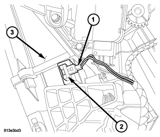
NOTE: LHD model shown. RHD model similar.
1. Disconnect and isolate the negative battery cable.
2. On LHD models, remove the instrument panel silencer from the driver side of the instrument panel (refer to 23 - BODY/INSTRUMENT PANEL/INSTRUMENT PANEL SILENCER - REMOVAL).
3. On RHD models, remove the glove box from the instrument panel (refer to 23 - BODY/INSTRUMENT PANEL/GLOVE BOX - REMOVAL).
4. Disconnect the HVAC wire harness connector (1) from the evaporator temperature sensor (2) located on the left side of the HVAC housing (3).
5. Remove the evaporator temperature sensor from the HVAC housing.
INSTALLATION
NOTE: LHD model shown. RHD model similar.
1. Install the evaporator temperature sensor (2) into the left side of the HVAC housing (3). Make sure that the sensor retaining clips are fully engaged in the housing.
2. Connect the HVAC wire harness connector (1) to the evaporator temperature sensor.
3. On LHD models, install the instrument panel silencer onto the driver side of the instrument panel (refer to 23 - BODY/INSTRUMENT PANEL/INSTRUMENT PANEL SILENCER - INSTALLATION).
4. On RHD models, install the glove box into the instrument panel (refer to 23 - BODY/INSTRUMENT PANEL/GLOVE BOX - INSTALLATION).
5. Reconnect the negative battery cable.