INSTALLATION
FRONT
WARNING: To avoid personal injury or death, on vehicles equipped with airbags, disable the supplemental restraint system before attempting any steering wheel, steering column, airbag, seat belt tensioner, impact sensor, or instrument panel component diagnosis or service. Disconnect and isolate the battery negative (ground) cable, then wait two minutes for the system capacitor to discharge before performing further diagnosis or service. This is the only sure way to disable the supplemental restraint system. Failure to take the proper precautions could result in accidental airbag deployment.
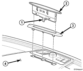
1. Align the bottom of the front park assist display (2) housing with the opening in the escutcheon (3).
2. Using hand pressure, push firmly and evenly on the lens of the display housing to engage the snap clips on the housing into the opening in the escutcheon.
3. Position the escutcheon and the display to the opening in the instrument panel top pad (4) as a unit to access and reconnect the instrument panel wire harness connector to the connector receptacle (1) on the bottom of the display housing.
4. Using hand pressure, push firmly and evenly on the top of the display lens to engage the latch features on the escutcheon into the opening in the instrument panel top pad.
5. Reconnect the battery negative cable.
REAR
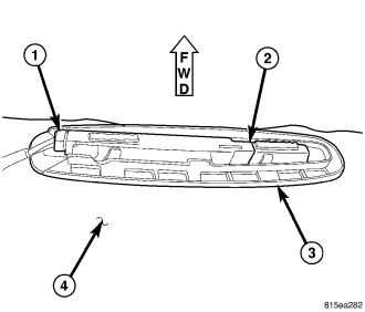
1. Carefully position the rear park assist display (2) through the opening in the face of the headliner (4) with the connector receptacle oriented toward the left side of the vehicle.
2. With the display lens held flush against the face of the headliner, position the molded plastic retainer (3) over the display housing and flush against the headliner substrate.
3. Slide the retainer toward the right side of the vehicle to lock the display into place.
4. Reconnect the wire harness connector (1) to the connector receptacle on the left end of the display housing.
5. Reinstall the trim onto both upper D-pillars. (Refer to 23 - BODY/INTERIOR/D-PILLAR TRIM - INSTALLATION).
6. Reinstall the trim onto the upper liftgate opening. (Refer to 23 - BODY/INTERIOR/LIFTGATE OPENING UPPER TRIM - INSTALLATION).
7. Reconnect the battery negative cable.