OUTLETS-AIR
DESCRIPTION
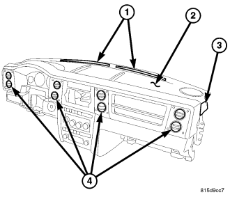
There are two defroster air outlets (1) located on the top of the instrument panel (2). The airflow from the defroster outlets is directed by fixed vanes in the defroster grille and cannot be adjusted. The defroster grille is serviced separately, however, the defroster outlets are not serviceable from the instrument panel top cover (refer to 23 - BODY/INSTRUMENT PANEL/INSTRUMENT PANEL TOP COVER - REMOVAL).
There are two side window demister air outlets (3). One located on each end of the instrument panel top cover. The airflow from the side window demister air outlets is directed by fixed vanes in the outlets and cannot be adjusted. The side window demister air outlets are not serviceable from the instrument panel top cover (refer to 23 - BODY/INSTRUMENT PANEL/INSTRUMENT PANEL TOP COVER - REMOVAL).
There are eight instrument panel air outlets (4). Two air outlets are located near each outboard end of the instrument panel facing the rear of the vehicle and two outlets are located on each side of the radio bezel. Each of the instrument panel air outlets contain a non-serviceable grille with movable vanes that are used to direct or shut off the flow of the conditioned air leaving the instrument panel outlets. All of the instrument panel air outlets can be serviced separately.
REMOVAL
WARNING: Disable the airbag system before attempting any steering wheel, steering column, or instrument panel component diagnosis or service. Disconnect and isolate the battery negative (ground) cable, then wait two minutes for the airbag system capacitor to discharge before performing further diagnosis or service. This is the only sure way to disable the airbag system. Failure to take the proper precautions could result in accidental airbag deployment and possible personal injury or death.
NOTE: Take the proper precautions to protect the front face of the instrument panel bezel from cosmetic damage while performing this procedure.
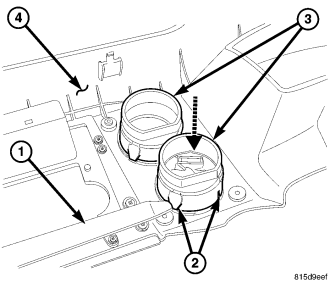
1. Remove the instrument panel bezel from the instrument panel and place the bezel on a workbench (refer to 23 - BODY/INSTRUMENT PANEL/BEZEL-INSTRUMENT PANEL - REMOVAL).
2. Using a trim stick or another suitable wide flat-blade tool (1), release the three retaining clips (2) that secure each instrument panel air outlet (3) to the instrument panel bezel (4) and remove the air outlets as necessary.
INSTALLATION
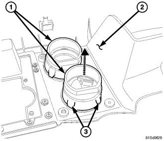
NOTE: Make sure that the air outlet is properly aligned to the instrument panel duct and that the foam seal on the outlet is not damaged.
1. Align the instrument panel air outlets (1) to the openings of the instrument panel ducts and install the air outlets into the instrument panel bezel (2) as necessary. Make sure that each of the air outlet's three retaining clips (3) are fully engaged to the instrument panel bezel.
2. Install the instrument panel bezel onto the instrument panel (refer to 23 - BODY/INSTRUMENT PANEL/BEZEL-INSTRUMENT PANEL - INSTALLATION).