ROCKER ARM - VALVE
DESCRIPTION
The rocker arms are steel stampings with an integral roller bearing. The rocker arms incorporate an 0.5 mm (0.019 inch) oil hole in the ball socket for roller and camshaft lubrication.
REMOVAL
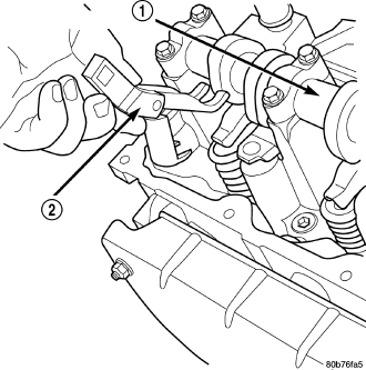
NOTE: Disconnect the battery negative cable to prevent accidental starter engagement.
1. Remove the cylinder head cover (Refer to 9 - ENGINE/CYLINDER HEAD/CYLINDER HEAD COVER(S) - REMOVAL).
2. For rocker arm removal on cylinders 3 and 5 Rotate the crankshaft until cylinder #1 is at TDC exhaust stroke.
3. For rocker arm removal on cylinders 2 and 8 Rotate the crankshaft until cylinder #1 is at TDC compression stroke.
4. For rocker arm removal on cylinders 4 and 6 Rotate the crankshaft until cylinder #3 is at TDC compression stroke.
5. For rocker arm removal on cylinders 1 and 7 Rotate the crankshaft until cylinder #2 is at TDC compression stroke.
6. Using special tool 8516 Rocker Arm Remover (2), press downward on the valve spring, remove rocker arm.
INSTALLATION
CAUTION: Make sure the rocker arms are installed with the concave pocket over the lash adjusters. Failure to do so may cause severe damage to the rocker arms and/or lash adjusters.
NOTE: Coat the rocker arms with clean engine oil prior to installation.
1. For rocker arm installation on cylinders 3 and 5 Rotate the crankshaft until cylinder #1 is at TDC exhaust stroke.
2. For rocker arm installation on cylinders 2 and 8 Rotate the crankshaft until cylinder #1 is at TDC compression stroke.
3. For rocker arm installation on cylinders 4 and 6 Rotate the crankshaft until cylinder #3 is at TDC compression stroke.
4. For rocker arm installation on cylinders 1 and 7 Rotate the crankshaft until cylinder #2 is at TDC compression stroke.
5. Using special tool 8516 press downward on the valve spring, install rocker arm .
6. Install the cylinder head cover (Refer to 9 - ENGINE/CYLINDER HEAD/CYLINDER HEAD COVER(S) - INSTALLATION).