CYLINDER HEAD
- OPERATION-CYLINDER HEAD
- DIAGNOSIS AND TESTING - CYLINDER HEAD GASKET FAILURE
- REMOVAL
- CLEANING
- INSPECTION
- INSTALLATION
OPERATION-CYLINDER HEAD
The cylinder head closes the combustion chamber allowing the pistons to compress the air fuel mixture to the correct ratio for ignition. The valves located in the cylinder head open and close to either allow clean air into the combustion chamber or to allow the exhaust gases out, depending on the stroke of the engine.DIAGNOSIS AND TESTING - CYLINDER HEAD GASKET FAILURE
A cylinder head gasket leak can be located between adjacent cylinders or between a cylinder and the adjacent water jacket.
- Possible indications of the cylinder head gasket leaking between adjacent cylinders are:
- Loss of engine power
- Engine misfiring
- Poor fuel economy
- Possible indications of the cylinder head gasket leaking between a cylinder and an adjacent water jacket are:
- Engine overheating
- Loss of coolant
- Excessive steam (white smoke) emitting from exhaust
- Coolant foaming
CYLINDER-TO-CYLINDER LEAKAGE TEST
To determine if an engine cylinder head gasket is leaking between adjacent cylinders, follow the procedures in Cylinder Compression Pressure Test in this section. An engine cylinder head gasket leaking between adjacent cylinders will result in approximately a 50–70% reduction in compression pressure.
CYLINDER-TO-WATER JACKET LEAKAGE TEST
WARNING: USE EXTREME CAUTION WHEN THE ENGINE IS OPERATING WITH COOLANT PRESSURE CAP REMOVED.
VISUAL TEST METHOD
With the engine cool, remove the coolant pressure cap. Start the engine and allow it to warm up until thermostat opens.
If a large combustion/compression pressure leak exists, bubbles will be visible in the coolant.
COOLING SYSTEM TESTER METHOD
WARNING: WITH COOLING SYSTEM TESTER IN PLACE, PRESSURE WILL BUILD UP FAST. EXCESSIVE PRESSURE BUILT UP, BY CONTINUOUS ENGINE OPERATION, MUST BE RELEASED TO A SAFE PRESSURE POINT. NEVER PERMIT PRESSURE TO EXCEED 138 kPa (20 psi).
Install Cooling System Tester 7700 or equivalent to pressure cap neck. Start the engine and observe the tester's pressure gauge. If gauge pulsates with every power stroke of a cylinder a combustion pressure leak is evident.
CHEMICAL TEST METHOD
Combustion leaks into the cooling system can also be checked by using Bloc-Chek Kit C-3685-A or equivalent. Perform test following the procedures supplied with the tool kit.
REMOVAL
1. Perform the Fuel System Pressure Release procedure (Refer to 14 - FUEL SYSTEM/FUEL DELIVERY - STANDARD PROCEDURE). Disconnect the fuel supply line (Refer to 14 - FUEL SYSTEM/FUEL DELIVERY/QUICK CONNECT FITTING - STANDARD PROCEDURE).
2. Disconnect the battery negative cable.
3. Drain cooling system (Refer to 7 - COOLING - STANDARD PROCEDURE) .
4. Remove the air cleaner resonator and duct work (Refer to 9 - ENGINE/AIR INTAKE SYSTEM - REMOVAL) .
5. Remove closed crankcase ventilation system.
6. Disconnect the exhaust at the exhaust manifolds.
7. Disconnect the evaporation control system.
8. Disconnect heater hoses.
9. Remove the power steering pump.
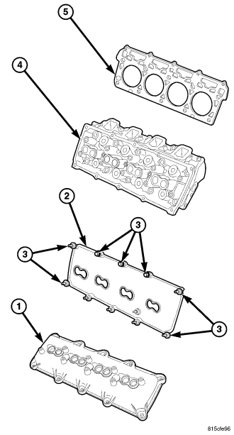
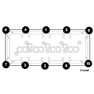
10. Remove cylinder head covers (1), using the sequence provided, and gaskets (2). (Refer to 9 - ENGINE/CYLINDER HEAD/CYLINDER HEAD COVER(S) - REMOVAL) .
11. Remove intake manifold and throttle body as an assembly. (Refer to 9 - ENGINE/MANIFOLDS/INTAKE MANIFOLD - REMOVAL).
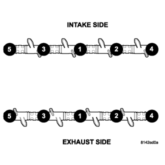
12. Remove rocker arm assemblies and push rods. Identify to ensure installation in original locations. (Refer to 9 - ENGINE/CYLINDER HEAD/ROCKER ARM / ADJUSTER ASSY - REMOVAL) .
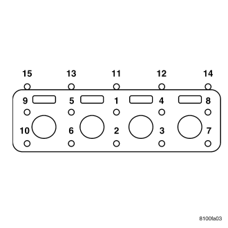
13. Remove the head bolts from each cylinder head, using the sequence provided, and remove cylinder heads. Discard the cylinder head gasket.
CLEANING
Clean all surfaces of cylinder block and cylinder heads.
Clean cylinder block front and rear gasket surfaces using a suitable solvent.
INSPECTION
1. Inspect the cylinder head for out-of-flatness, using a straightedge and a feeler gauge. If tolerances exceed 0.0508 mm (0.002 in.) replace the cylinder head.
2. Inspect the valve seats for damage. Service the valve seats as necessary.
3. Inspect the valve guides for wear, cracks or looseness. If either condition exist, replace the cylinder head.
4. Inspect pushrods. Replace worn or bent pushrods.
INSTALLATION
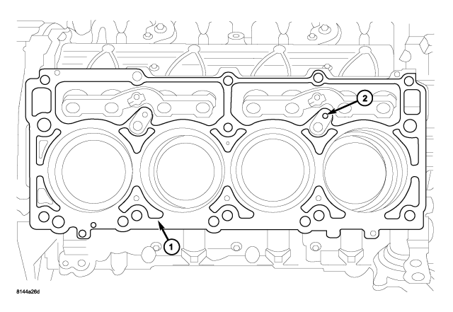
1. Clean all surfaces of cylinder block and cylinder heads.
2. Clean cylinder block front and rear gasket surfaces using a suitable solvent.
CAUTION: The head gaskets (1) are not interchangeable between left and right sides. They are marked “L” and “R” to indicate left and right sides.
CAUTION: The head gaskets (1) are marked “TOP” to indicate which side goes up.
3. Position new cylinder head gaskets (5) onto the cylinder block.
4. Position cylinder heads (4) onto head gaskets (5) and cylinder block.
5. Tighten the cylinder head bolts in three steps using the sequence provided :
- Step 1— Snug tighten M12 cylinder head bolts, in sequence, to 34 N·m (25 ft. lbs.) and M8 bolts to 20 N·m (15 ft. lbs.) torque.
- Step 2— Tighten M12 cylinder head bolts, in sequence, to 54 N·m (40 ft. lbs.) and verify M8 bolts to 20 N·m (15 ft. lbs.) torque..
- Step 3— Turn M12 cylinder head bolts, in sequence, 90 degrees and tighten M8 bolts to 34 N·m (25 ft. lbs.) torque.
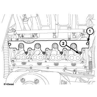
6. Install push rods and rocker arm assemblies in their original position, using pushrod retaining plate (1) special tool# 9070. (Refer to 9 - ENGINE/CYLINDER HEAD/ROCKER ARM / ADJUSTER ASSY - INSTALLATION) .
7. Install the intake manifold and throttle body assembly (Refer to 9 - ENGINE/MANIFOLDS/INTAKE MANIFOLD - INSTALLATION).
8. If required, adjust spark plugs to specifications. Install the plugs.
9. Connect the heater hoses.
10. Install the fuel supply line.
11. Install the power steering pump.
12. Install the drive belt (Refer to 7 - COOLING/ACCESSORY DRIVE/DRIVE BELTS - INSTALLATION) .
13. Install cylinder head covers (1) (Refer to 9 - ENGINE/CYLINDER HEAD/CYLINDER HEAD COVER(S) - INSTALLATION) .
14. Connect the evaporation control system.
15. Install the air cleaner (Refer to 9 - ENGINE/AIR INTAKE SYSTEM - INSTALLATION) .
16. Fill cooling system (Refer to 7 - COOLING - STANDARD PROCEDURE) .
17. Connect the negative cable to the battery.
18. Start engine check for leaks.