STANDARD PROCEDURE
PCM/ECM REPROGRAMMING
MODULE REPROGRAMING
Replacement PCM's will require programming utilizing the StarSCAN® or equivalent. The PCM will not operate the engine until it is programmed. A Diagnostic Trouble Code (DTC) will be set - “not programmed”.
CAUTION: Extreme care must be taken when programming a calibration into a generic PCM. Do not randomly select a calibration. Once a calibration is selected and programmed, the controller cannot be reprogrammed to a different calibration. The module can only be reprogrammed to a more recent version of that calibration.
SPECIAL TOOLS/EQUIPMENT OR EQUIVALENT REQUIRED:
| NPN | Battery Charger |
| CH9401 | StarSCAN® Tool |
| CH9404 | StarSCAN® Vehicle Cable |
| CH9409 | StarSCAN® Documentation Kit |
| CH9410 | StarSCAN® Ethernet Cable, 12 ft. |
| CH9412 | StarSCAN® Software Update Device Kit |
| TechCONNECT PC or equivalent | |
| StarSCAN® Software Update CD |
**REPAIR PROCEDURE - USING THE INTERNET TO RETRIEVE THE FLASH FILE:
NOTE: The StarSCAN® or equivalent diagnostic scan tool fully supports Internet connectivity. However, in order to take advantage of this feature you must first configure the StarSCAN® or equivalent for your dealership's network. For instruction on setting up your StarSCAN® or equivalent for the dealer's network; refer to the StarSCAN® or equivalent Quick Start Networking Guide available on DealerCONNECT > Service > StarSCAN® or equivalent and StarMOBILE Tools > Online Documentation or at www.dcctools.com website under the "download center".
NOTE: If this flash process is interrupted/aborted, the flash should be restarted.
1. Open the hood, install a battery charger and verify that the charging rate provides approximately 13.5 volts. Set the battery charger timer to maintain the charging voltage for the duration of the flash process.
2. Connect the CH9410 StarSCAN® or equivalent ethernet cable to the StarSCAN® or equivalent and the dealer's network drop.
3. Connect the CH9404 StarSCAN® or equivalent vehicle cable to the StarSCAN® or equivalent and the vehicle.
4. Power ON the StarSCAN®; or equivalent.
5. Retrieve the old ECU part number. Using the StarSCAN® or equivalent at the “Home” screen:
a. Select “ECU View”
b. Touch the screen to highlight the PCM in the list of modules.
c. Select “More Options”
d. Select “ECU Flash”
e. Record the part number at the top of the “Flash PCM” screen for later reference.
6. Replace the PCM with the appropriate Generic PCM. Refer to the detailed service information available in TechCONNECT, under: Service Info, 8-Electrical, Electronic Control Module, Powertrain Control Module, Removal.
7. Program the PCM as follows:
a. Using the StarSCAN® or equivalent at the “Home” screen, Select “ECU View”
b. Touch the screen to highlight the PCM in the list of modules.
c. Select “More Options”
d. Select “ECU Flash”
e. Select “Browse for New File”. Follow the on screen instructions.
f. Highlight the appropriate calibration based on the part number recorded in Step 5.
g. Select “Download to Scantool”.
h. Select “Close” after the download is complete, then select “Back”.
i. Highlight the listed calibration.
j. Select “Update Controller”. Follow on screen instructions.
** When the update is complete, select “OK”.
** Verify the part number at the top of the “Flash PCM” screen has updated to the new part number.
8. Is “WCM - Wireless Control Module” displayed in the “ECU Overview” screen list of modules?
a. Yes >> go to STEP 9.
b. No >> go to STEP 10.
9. Program the PCM to the Wireless Control Module (WCM).
a. Highlight the WCM.
b. Select “Misc. Function”.
c. Highlight “PCM Replaced”.
d. Select “Start”
e. Follow the on screen instructions. Select “Next” after each step . Select “Finish” after completing the last step.
f. When complete proceed to STEP 11.
10. Program the VIN into the PCM.
a. Scroll through the list of controllers and highlight the PCM.
b. Select “Misc. Function”.
c. Highlight “Check PCM VIN”.
d. Select “Start”
e. Follow the on screen instructions. Select “Next” after each step . When the window appears with 17 boxes, select “Show Keyboard”. Place the cursor to the right of the last box and then backspace to delete the boxes from the window. Enter the VIN. Select “Finish” after completing the last step.
f. Unplug the scan tool from the Data Link Connector.
g. At the “Vehicle Disconnected” screen, press “OK”.
h. Connect the scan tool to the Data Link Connector and verify that the VIN is visible at the top of the “Home” screen.
11. Is the vehicle is equipped with a 3.7L or 4.7L engine?
a. Yes >> go to STEP 13.
b. No >> go to STEP 12.
12. Using the StarSCAN® or equivalent at the “Home” screen:
a. Select “ECU View”
b. Scroll through the list of controllers and highlight the PCM.
c. Select “Misc. Function”.
d. Highlight “Learn ETC”.
e. Select “Start”
f. Follow the on screen instructions. Select “Next” after each step . Select “Finish” after completing the last step.
NOTE: Due to the PCM programming procedure, a DTC may be set in other modules (TCM, BCM, MIC, SKREEM, etc.) within the vehicle, if so equipped. Some DTC's may cause the MIL to illuminate. From the “Home” screen select “System View”. Then select “All DTCs”. Press “Clear All Stored DTCs” if there are any DTCs shown on the list.
NOTE: The following step is required by law when reprogramming a PCM and/or TCM.
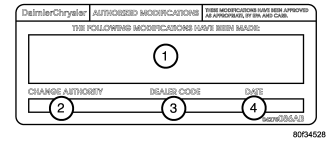
13. Type the necessary information on the “Authorized Modification Label” p/n 04275086AB and attach near the VECI label .
REPAIR PROCEDURE USING SOFTWARE UPDATE CD TO RETRIEVE THE FLASH FILE:
NOTE: If this flash process is interrupted/aborted, the flash should be restarted.
NOTE: For detailed information on the operation of the StarSCAN® or equivalent, refer to the Quick Reference documentation provided in the StarSCAN® or equivalent documentation kit. In addition, more recent information may also be available at the www.dcctools.com website. Look under "Training Aids" and also under "Download Center > Frequently Asked Questions" for more help.
1. Open the hood, install a battery charger and verify that the charging rate provides approximately 13.5 volts. Set the battery charger timer to maintain the charging voltage for the duration of the flash process.
2. Connect the CH9404 StarSCAN® or equivalent vehicle cable to the StarSCAN® or equivalent and the vehicle.
3. Power ON the StarSCAN® or equivalent.
4. Retrieve the old ECU part number. Using the StarSCAN® or equivalent at the “Home” screen:
a. Select “ECU View”
b. Touch the screen to highlight the PCM in the list of modules.
c. Select “More Options”
d. Select “ECU Flash”
e. Record the part number at the top of the “Flash PCM” screen for later reference.
5. Replace the PCM with the appropriate Generic PCM. Refer to the detailed service information available in TechCONNECT, under: Service Info, 8-Electrical, Electronic Control Module, Powertrain Control Module, Removal.
6. Insert the StarSCAN® or equivalent Software Update CD into the TechCONNECT or equivalent PC. The StarSCAN® or equivalent Software Update CD will start automatically. Select “Download Flash Updates”.
7. At the “Select a method for looking up controller flash updates.” screen:
a. Select “Enter part number”. Enter the “Part Number” recorded in STEP 4 when prompted to do so.
b. Using the mouse highlight the appropriate “Calibration”. Select “Next”.
c. Follow the on screen instructions.
d. When completed, proceed to STEP 8.
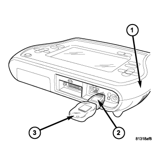
8. With the StarSCAN® or equivalent powered OFF, connect the USB Key and Gender Changer to the StarSCAN® or equivalent® USB port .
9. Connect the StarSCAN® or equivalent to the vehicle (if not already connected).
10. Power ON the StarSCAN® or equivalent.
11. Download the flash file from the USB key to the StarSCAN® or equivalent. Using the StarSCAN® or equivalent at the “Home” screen:
a. Select “Flash Download”, then select “Retrieve files from the USB storage device”
b. Highlight the appropriate calibration. Select “Download to Scan Tool”
c. When the download is complete, select “Close” and “Back”.
12. Reprogram the ECU. Using the StarSCAN® or equivalent at the “Home” screen:
a. Select “ECU View”.
b. Select "More Options”.
c. Select “ECU Flash”.
d. Highlight the appropriate calibration.
e. Select “Update Controller”. Follow the on screen instructions.
f. When the update is complete, select “OK”.
g. Verify the part number at the top of the “Flash PCM” screen has updated to the new part number.
13. Is “WCM - Wireless Control Module” displayed in the “ECU Overview” screen list of modules?
a. Yes >> go to STEP 14.
b. No >> go to STEP 15.
14. Program the PCM to the Wireless Control Module (WCM). Using the StarSCAN® or equivalent at the “Home” screen:
a. Select “ECU View”
b. Scroll through the list of controllers and highlight the WCM.
c. Select “Misc. Function”.
d. Highlight “PCM Replaced”.
e. Select “Start”
f. Follow the on screen instructions. Select “Next” after each step . Select “Finish” after completing the last step.
g. When complete proceed to STEP 16.
15. Program the VIN into the PCM.
a. Scroll through the list of controllers and highlight the PCM.
b. Select “Misc. Function”.
c. Highlight “Check PCM VIN”.
d. Select “Start”
e. Follow the on screen instructions. Select “Next” after each step . When the window appears with 17 boxes, select “Show Keyboard”. Place the cursor to the right of the last box and then backspace to delete the boxes from the window. Enter the VIN. Select “Finish” after completing the last step.
f. Unplug the scan tool from the Data Link Connector.
g. At the “Vehicle Disconnected” screen, press “OK”.
h. Connect the scan tool to the Data Link Connector and verify that the VIN is visible at the top of the “Home” screen.
16. Is the vehicle is equipped with a 3.7L or 4.7L engine?
a. Yes >> go to STEP 18.
b. No >> go to STEP 17.
17. Using the StarSCAN® or equivalent at the “Home” screen:
a. Select “ECU View”
b. Scroll through the list of controllers and highlight the PCM.
c. Select “Misc. Function”.
d. Highlight “Learn ETC”.
e. Select “Start”
f. Follow the on screen instructions. Select “Next” after each step . Select “Finish” after completing the last step.
NOTE: Due to the PCM programming procedure, a DTC may be set in other modules (TCM, BCM, MIC, SKIM, etc.) within the vehicle, if so equipped. Some DTC's may cause the MIL to illuminate. Check all modules using “ECU View” from the Home screen, record the DTC's, and erase these DTC's prior to returning the vehicle to the customer. Erase any DTC's in the PCM only after all other modules have had their DTC's erased.
NOTE: The following step is required by law.
18. Type the necessary information on the “Authorized Modification Label” p/n 04275086AB and attach near the VECI label . **
POWERTRAIN VERIFICATION TEST
For a complete wiring diagram Refer to Section 8W.
Diagnostic Test
1. SELECTING THE PROPER VERIFICATION TESTThe following verification test are for different repairs . Select the appropriate Verification test for the repair that has been completed.
Speed Control repair
- Go To 2
Charging System repair
- Go To 3
NVLD System repair
- Go To 4
All other repairs
- Go To 5
2. POWERTRAIN VERIFICATION TEST 1
NOTE: 1. If this vehicle is equipped with an Electronic Throttle Control system, and the APP Sensors, PCM, or Throttle Body Assembly have been replaced, use the scan tool to perform the ETC RELEARN function.
NOTE: 2. After completing the Powertrain Verification Test the Transmission Verification Test must be performed.
NOTE: 3. If the PCM has been replaced and the correct VIN and mileage have not been programmed, a DTC will set in the ABS Module, Airbag Module and the SKIM/SKREEM.
NOTE: 4. If the vehicle is equipped with a Sentry Key Remote Entry, Secret Key data must be updated. Refer to the Service Information for the PCM, SKIM/SKREEM and the Transponder (ignition key) for programming information. Using the scan tool, program the Secret Key information into the PCM using the PCM replaced function under the WCM menu.
5. Inspect the vehicle to make sure that all engine components are properly installed and connected.
6. Connect the scan tool to the data link connector and erase all codes.
7. Turn the speed control ON (if equipped, cruise light will be on).
8. Depress and release the SET Switch when the vehicle speed is greater than 56 km/h (35 mph). The speed control should engage and hold the selected speed.
9. Press and hold the RESUME/ACCEL Switch. The vehicle speed should increase by at least 3 km/h (2 mph).
10. Press and hold the COAST switch. The vehicle speed should decrease.
11. Using caution, press and release the brake pedal. The speed control should disengage.
12. Bring the vehicle speed back up to 56 km/h (35 mph).
13. Press the RESUME/ACCEL switch. The speed control should resume the previously set speed.
14. Hold down the SET switch. The vehicle should decelerate.
15. Make sure vehicle speed is greater than 56 km/h (35 mph) and release the SET Switch. The vehicle should adjust and set a new vehicle speed.
16. Press and release the CANCEL switch. The speed control should disengage.
17. Bring the vehicle speed back up above 56 km/h (35 mph) and engage speed control.
18. Turn the Speed Control Off. (Cruise light will be off). The speed control should disengage.
NOTE: OVERSHOOT/UNDERSHOOT FOLLOWING SPEED CONTROL SET.
19. If the vehicle operator repeatedly presses and releases the SET button with their foot off of the accelerator (referred to as "lift foot set"), the vehicle may accelerate and exceed the desired set speed by up to 8 km/h (5 mph).
20. It may also decelerate to less than the desired set speed, before finally achieving the desired set speed.
21. The Speed Control System has an adaptive strategy that compensates for vehicle-to-vehicle variations in speed control cable lengths.
22. When the speed control is set with the vehicles operators foot off of the accelerator pedal, the speed control thinks there is excessive speed control cable slack and adapts accordingly.
23. If the "lift foot sets" are continually used, a speed control overshoot/undershoot condition will develop.
24. To "unlearn" the overshoot/undershoot condition, the vehicle operator has to press and release the set button while maintaining the desired set speed using the accelerator pedal (not decelerating or accelerating).
25. Then turn the cruise control switch to the OFF position (or press the CANCEL button if equipped) after waiting 10 seconds.
26. This procedure must be performed approximately 10-15 times to completely unlearn the overshoot/undershoot condition.
Did the Speed Control pass the above test?
Yes
- Repair is complete.
No
- Check for any related Technical Service Bulletins and/or refer to the appropriate Diagnostic Procedure.
3. POWERTRAIN VERIFICATION TEST 2
1. If this vehicle is equipped with an Electronic Throttle Control system, and the APP Sensors, PCM, or Throttle Body Assembly has been replaced use a scan tool to perform the ETC RELEARN function.
NOTE: 2. After completing the Powertrain Verification Test the Transmission Verification Test must be performed.
NOTE: 3. If the PCM has been replaced and the correct VIN and mileage have not been programmed, a DTC will set in the ABS Module, Airbag Module and the SKIM/SKREEM.
NOTE: 4. If the vehicle is equipped with a Sentry Key Remote Entry, Secret Key data must be updated. Refer to the Service Information for the PCM, SKIM/SKREEM and the Transponder (ignition key) for programming information. Using the scan tool, program the Secret Key information into the PCM using the PCM replaced function under the WCM menu.
5. Inspect the vehicle to make sure that all components related to the repair are properly installed and connected.
6. With the scan tool, clear DTCs.
7. Perform generator output test. Refer to the appropriate service information as necessary.
8. Start the engine and set engine speed to 2000 RPM for at least thirty seconds.
9. Cycle the ignition key off and on.
10. With the scan tool, read the DTCs.
Are any DTCs or symptoms remaining?
Yes
- Check for any Technical Service Bulletins and/or refer to the appropriate Diagnostic Procedure.
No
- Repair is complete.
4. POWERTRAIN VERIFICATION TEST 3
1. Install the Miller Tool #8404 Evaporative Emission Leak Detector (EELD) according to the instructions in the previous DTC table.
2. Set the smoke/air control switch to AIR.
3. Insert the tester's AIR supply tip (clear hose) into the appropriate calibration orifice on the tester's control panel (based on DTC leak size).
4. Press the remote smoke/air start button.
5. Position the red flag on the air flow meter so it is aligned with the indicator ball.
6. When the calibration is complete, release the remote button. The EELD flow meter is now calibrated in liters per minute to the size of leak indicated by the DTC set in the PCM.
7. Install the service port adapter #8404-14 on the vehicle's service port.
8. Connect the Air supply hose from the EELD to the vehicle.
9. Press the remote button to activate AIR flow.
NOTE: 10. Larger volume fuel tanks, lower fuel levels or if the vehicle is equipped with a Flow Management Valve may indicate high flow and will require 4 to 5 minutes to fill.
11. Compare the flow meter indicator ball reading to the red flag.
12. ABOVE the red flag indicates a leak present.
13. BELOW the red flag indicates a sealed system.
NOTE: If this vehicle is equipped with an Electronic Throttle Control system, and the APP Sensors, PCM, or Throttle Body Assembly have been replaced, use the scan tool to perform the ETC RELEARN function.
14. If the indicator ball shows a leak present, perform the smoke test indicated in the previous test and identify the leak and repair. Perform this verification test when the repair is complete.
Did the indicator ball indicate the a leak is present?
Yes
- Repeat the DTC test to identify the leak and repair.
No
- Repair is complete.
5. POWERTRAIN VERIFICATION TEST 4
NOTE: 1. After completing the Powertrain Verification Test the Transmission Verification Test must be performed.
NOTE: 2. If the PCM has been replaced and the correct VIN and mileage have not been programmed, a DTC will set in the ABS Module, Airbag Module and the SKIM/SKREEM.
NOTE: 3. If the vehicle is equipped with a Sentry Key Remote Entry, Secret Key data must be updated. Refer to the Service Information for the PCM, SKIM/SKREEM and the Transponder (ignition key) for programming information. Using the scan tool, program the Secret Key information into the PCM using the PCM replaced function under the WCM menu.
NOTE: 4. If this vehicle is equipped with an Electronic Throttle Control system, and the APP Sensors, PCM, or Throttle Body Assembly have been replaced, use the scan tool to perform the ETC RELEARN function.
NOTE: 5. When replacing an O2 Sensor, the PCM RAM memory must be cleared, either by disconnecting the PCM C1 connector or momentarily disconnecting the Battery negative terminal.
6. The NGC learns the characteristics of each O2 heater element and these old values should be cleared when installing a new O2 sensor. The customer may experience driveability issues if this is not performed.
7. Inspect the vehicle to make sure that all engine components are properly installed and connected. Reassemble and reconnect components as necessary.
8. Connect the scan tool to the data link connector.
9. Make sure the fuel tank has at least a quarter tank of fuel. Turn off all accessories.
10. If the Catalyst was replaced, with the scan tool go to the Miscellaneous Menu Option "Catalyst Replaced" and press enter.
11. If a Comprehensive Component DTC was repaired, perform steps 12 - 14. If a Major OBDII Monitor DTC was repaired skip those steps and continue verification.
12. After the ignition has been off for at least 10 seconds, restart the vehicle and run 2 minutes.
13. With the scan tool, monitor the appropriate pre-test enabling conditions until all conditions have been met. Once the conditions have been met, switch screen to the appropriate OBDII monitor, (Audible beeps when the monitor is running).
14. If the repaired OBDII trouble code has reset or was seen in the monitor while on the road test, the repair is not complete. Check for any related technical service bulletins or flash updates and return to Engine Electrical Diagnostic List.
15. If the conditions cannot be duplicated, erase all DTCs with the Scan tool.
16. If another DTC has set, return to the Engine Electrical Diagnostic List and follow the path specified for that DTC.
Did the OBDII Monitor run successfully and has the Good Trip Counter changed to one or more?
Yes
- Repair is complete.
No
- Check for any related Technical Service Bulletins and/or refer to the appropriate Diagnostic Procedure.