DIFFERENTIAL
REMOVAL
1. Remove half shafts and axle shaft.
2. Remove differential cover.
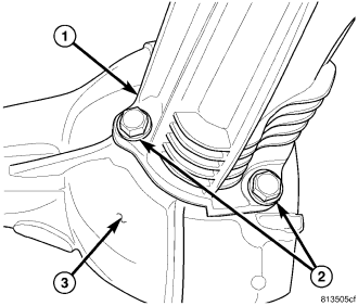
3. Remove three axle tube (1) mounting bolts (2) from differential housing (3).
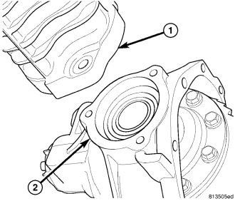
4. Tap axle tube (1) and pull tube off differential housing flange (2).
5. Remove half shaft differential housing seal with seal pick.
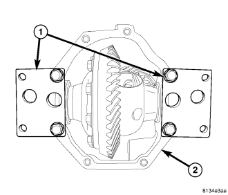
6. Bolt spreader Adapters 9669 (1) to differential housing (2).
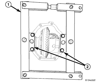
7. Install Spreader W-129-B (1) on adapters (2).
8. Spread case 0.3 mm (0.011 in.).
NOTE: Maximum case spread is 0.5 mm (0.02 in.).
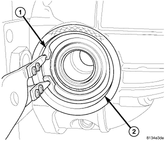
9. Remove select snap-rings (1) from differential housing bearing bores (2).
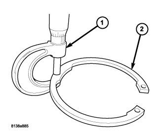
10. With a micrometer (1), measure select snap-rings (2) and mark the size and location of the snap-rings.
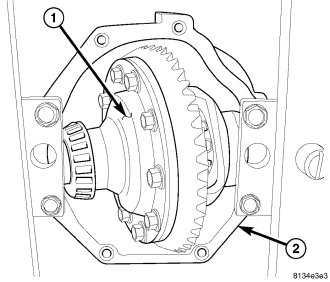
11. Tilt differential case (1) out of the housing (2) and remove case.
12. Loosen spreader.
DISASSEMBLY
1. Remove left hand thread ring gear bolts.
2. Drive ring gear of the case with a soft hammer.
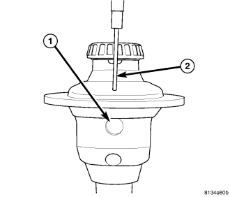
3. Remove pinion mate shaft (1) lock pin with a punch (2) and hammer.
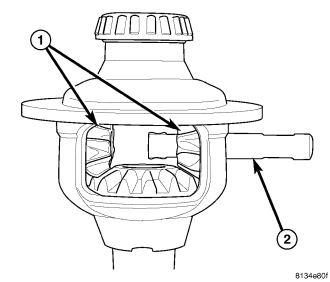
4. Remove pinion gears (1) mate shaft (2) from the case.
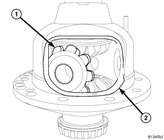
5. Rotate pinion gears (1) with washers to differential window (2) and remove gears through window.
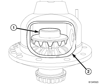
6. Remove upper side gear (1) through differential window (2).
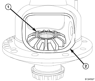
7. Remove lower side gear (1) through differential window (2).
ASSEMBLY
1. Install lower side gear (1) through differential window (2).
2. Install upper side gear (1) through differential window (2).
3. Install pinion gears (1) with washers into differential window (2) and rotate gears till aligned with pinion shaft hole.
4. Install pinion gears (1) mate shaft (2) into the case.
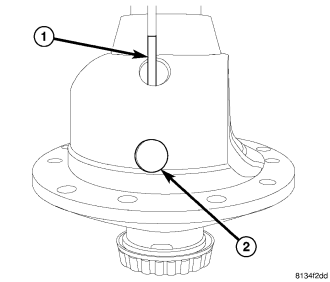
5. Install pinion mate shaft lock pin (1) with a hammer and punch, into the differential case and mate shaft (2).
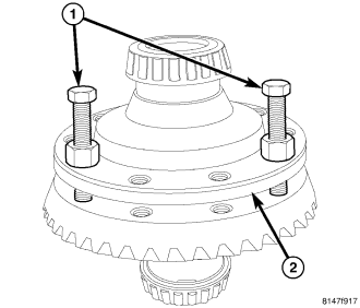
6. Install left hand thread ring gear Installer Bolts 9533 (1) through differential (2) and into ring gear. Tighten nuts on installer bolts evenly and draw ring gear onto differential case.
7. Remove installer bolts and install new ring gear bolts and tighten to 102 N·m (75 ft. lbs.).
INSTALLATION
1. Bolt spreader Adapters 9669 (1) to differential housing (2).
2. Install Spreader W-129-B (1) on adapters (2).
3. Spread case 0.3 mm (0.011 in.).
NOTE: Maximum case spread is 0.5 mm (0.02 in.).
4. Tilt differential case (1) into the housing (2).
5. Install bearing cups into their original housing bores.
6. Install one differential select snap-ring (1) into it's original housing bore (2).
7. Spread the housing and install the other differential select snap-ring.
8. Loosen the spreader.
9. Lube new o-ring and install on axle tube (1).
10. Align axle tube (1) with differential housing flange (2) and push tube into place.
CAUTION: The tube must be perfectly aligned to the housing to prevent damage to the O-ring. Failure to follow these instructions will result in a leak.
11. Install axle tube (1) bolts (2) and tighten to 56 N·m (41 ft. lbs.).
12. Install half shaft seal with Installer 9504 and Handle C-4171.
13. Apply a 6.35 mm (1/4 in.) bead of Mopar® Silicone Rubber RTV MS-GF44D or equivalent to the differential case.
CAUTION: If housing cover is not installed within 3 to 5 minutes, the differential case must be cleaned and new RTV applied. Failure to follow these instructions will result in a leak.
14. Install cover and tighten cover bolts in a criss-cross pattern to 56 N·m (41 ft. lbs.).