FRONT AXLE - C200FE
REMOVAL
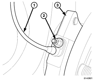
1. With vehicle in neutral, position vehicle on hoist.
2. Remove skid plate.
3. Remove differential housing drain plug and drain fluid.
4. Mark front propeller shaft and pinion flange. Remove propeller shaft from pinion flange.
5. Remove half shaft hub/bearing nuts.
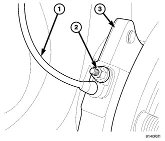
6. Remove wheel speed sensors (1) from hub/bearings (3).
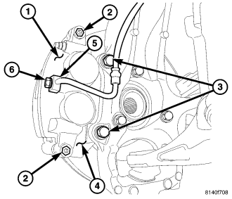
7. Remove brake calipers bolts (2) and remove calipers (1) from caliper adapters (4).
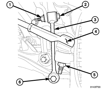
8. Remove stabilizer links (3) bolts (6) from lower control arms.
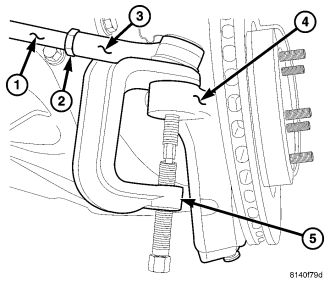
9. Remove outer tie rod end nuts and separate tie rods (3) from knuckles (4) with Remover 8677 (5).
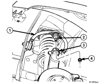
10. Remove upper ball joint nuts (4) and separate ball joints (2) from knuckles (3) with Remover 8677.
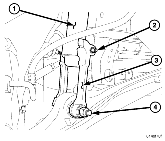
11. Remove lower shock clevis (3) nuts bolts (2) from lower control arm.
12. Lean the knuckles out and push half shafts out of the hub/bearings.
13. Pry half shafts off the axles.
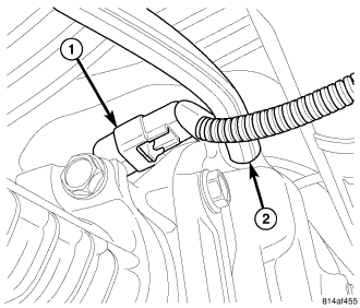
14. Remove ELSD connector (1) from axle.
15. Remove differential vent hose (2).
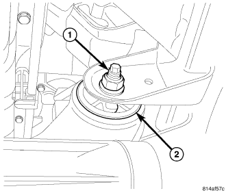
16. Remove bolt (1) from axle tube bushing (2).
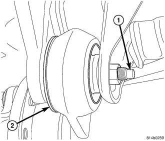
17. Remove bolt (1) from pinion nose bushing (2).
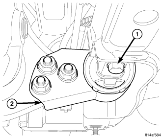
18. Support axle with a lift/jack.
19. Remove bolts (1) from differential cover bracket bushing (2).
20. Lower axle from vehicle.
INSTALLATION
1. Raise axle to vehicle.
2. Install pinion nose bushing (2) bolt (1) and nut. Tighten nut to 95 N·m (70 ft. lbs.)
3. Install axle tube bushing (2) bolt (1) and nut. Tighten nut to 95 N·m (70 ft. lbs.)
4. Install differential cover bracket bushing (2) bolts (1) and tighten bolts to 47 N·m (35 ft. lbs.)
5. Install ELSD connector (1) and differential vent hose (2).
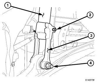
6. Install half shafts into axle and knuckles. Verify axles are engaged in the axle.
7. Install clevis (3) bolt and nut (4) on lower control arms and tighten to specification.
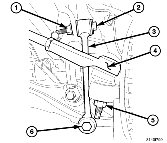
8. Install upper control arms on knuckles and tighten ball joint nuts to specifications.
9. Install tie rod ends (4) and nuts (5) on knuckles and tighten to specifications.
10. Install stabilizer bar links (3) and bolts (6) on lower control arms and tighten to specifications.
11. Install brake calipers on knuckles.
12. Install wheel speed sensor (1) on hub/bearing (3).
13. Install half shaft hub nuts and tighten to 135 N·m (100 ft. lbs.).
14. Install propeller shaft on pinion flange with reference marks aligned and tighten to 180 N·m (80 ft. lbs.).
15. Install drain plug and tighten to 60 N·m (44 ft. lbs.).
16. Fill differential housing and install fill plug. Tighten plug to 60 N·m (44 ft. lbs.).
17. Install skid plate.
SPECIAL TOOLS-C2OOFE
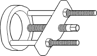
| PULLER/PRESS C-293-PA |
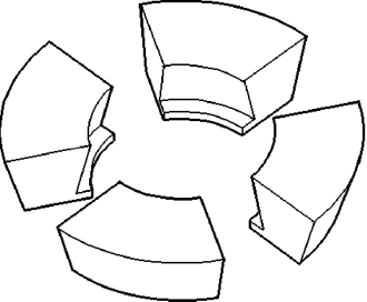
| ADAPTERS C-293-37 |
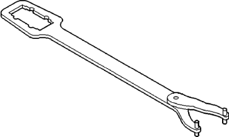
| WRENCH C-3281 |

| INSTALLER C-3972A |
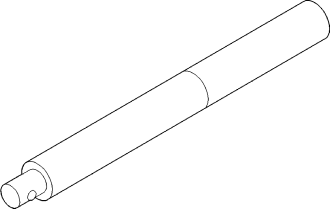
| HANDLE C-4171 |
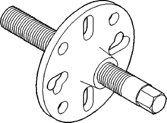
| PULLER C-452 |
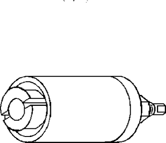
| REMOVER C-4660-A |
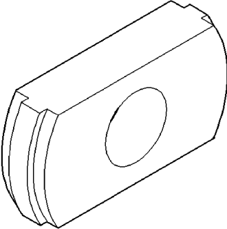
| REMOVER D-103 |
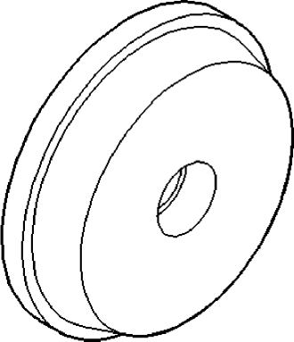
| INSTALLER D-111 |
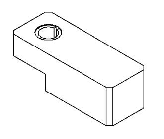
| SCOOTER BLOCK D-115-2A |
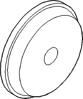
| INSTALLER D-129 |
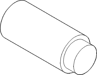
| PLUG SP-3289 |
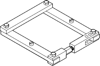
| SPREADER W-129-B |
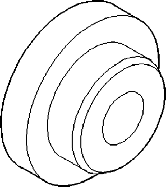
| INSTALLER 5063 |
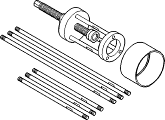
| PULLER 6444 |
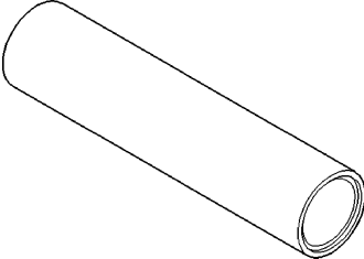
| INSTALLER 6448A |
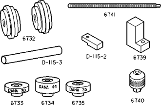
| PINION GAUGE SET 6774 |
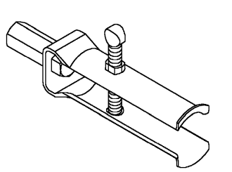
| REMOVER 7794-A |
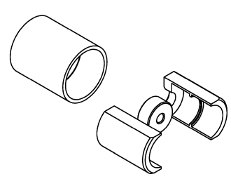
| REMOVER 8420A |
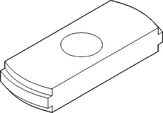
| REMOVER 9084 |
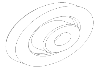
| INSTALLER 9504 |
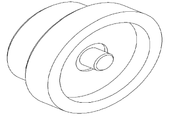
| RECEIVER/INSTALLER 9511 |
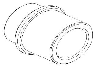
| REMOVER 9512 |
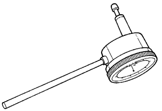
| DIAL INDICATOR 9524 |
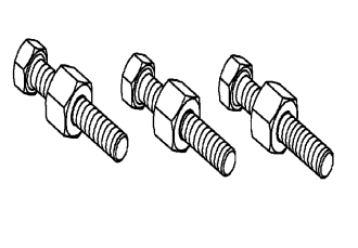
| RING GEAR INSTALLER 9533 |
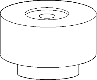
| PINION BLOCK 9534 |
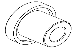
| INSTALLER 9535 |
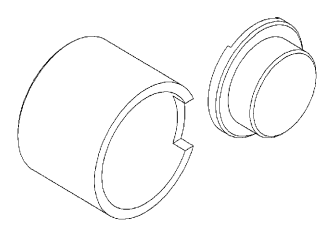
| RECEIVER 9536 |
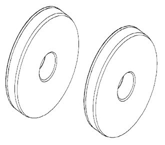
| ARBOR DISC 9538 |
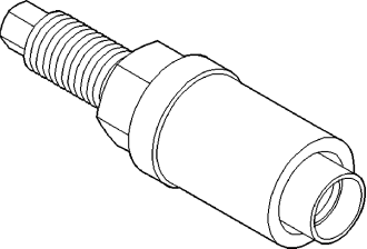
| INSTALLER 9616 |
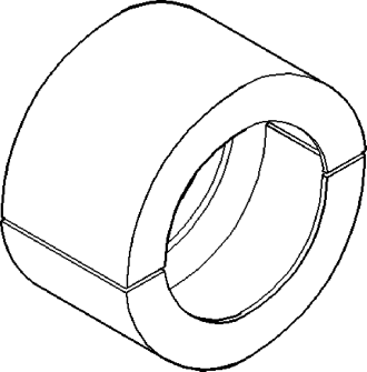
| JAWS 9641 |
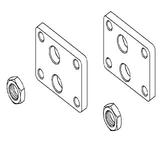
| SPREADER ADAPTERS 9669 |
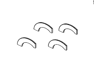
| DUMMY SNAP RINGS 9904 |
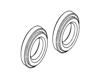
| DUMMY BEARINGS 9905 |