ACTUATOR-INTAKE PORT SWIRL
DESCRIPTION
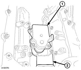
The intake manifold swirl actuator is located between the two intake manifolds .
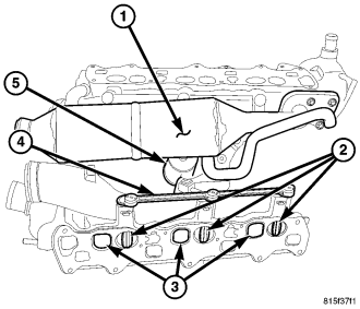
The intake manifolds have a charge air passage (3) which are ovate, and swirl passage (2) which are round, for each cylinder. The swirl blades (2) are mounted in each intake manifold swirl passage (2) and are not serviceable. The actuator (5) is PWM controlled by the ECM and is constantly adjusting while the engine is running to optimize the air/fuel mixture and create the best possible air turbulence. The result is Improved combustion, improved engine performance and a reduction in exhaust particulates. The swirl blades (2) in the intake manifold are held in the open position by an internal spring in an un-powered state .
OPERATION
There are two channels in each intake manifold for each cylinder. A charge air intake passage (3) and a swirl intake passage (2). The swirl passage (2) incorporates a blade (2) that is continually adjusted through linkage (4) and an actuator (5) when ever the engine is running. The actuator (5) is controlled by the ECM through a PWM signal. As engine speed and load increase the swirl channels adjust for optimized air turbulence and air mass requirements. When the engine is not running, the swirl channel blades (2) are held open by and integrated spring .
REMOVAL
1. Disconnect the negative battery cable.
2. Remove the engine cover.
3. Remove the strut tower support.
4. Drain the cooling system.
5. Remove the intake manifold (Refer to 9 - ENGINE/MANIFOLDS/INTAKE MANIFOLD - REMOVAL).
6. Position the intake manifolds on a work bench.
CAUTION: Care must be taken when disconnecting the actuator and rod assembly. Failure to do so will result in poor connections during assembly or intake manifold replacement.
7. Pinch together the actuating rod retaining clip and carefully separate the rod from the actuator.
8. Remove the actuator fasteners and actuator (1) from the intake manifold.
INSTALLATION
1. Position the actuator (1) on the intake manifold and tighten fasteners to 12N·m (106 in. lbs.).
CAUTION: Care must be taken when connecting the actuator and rod assembly. Failure to do so will result in poor connections during assembly or intake manifold replacement.
2. Carefully connect the relationship rod to the actuator. Do Not Force.
3. Install the intake manifold (Refer to 9 - ENGINE/MANIFOLDS/INTAKE MANIFOLD - INSTALLATION).
4. Install the turbocharger (Refer to 11 - EXHAUST SYSTEM/TURBOCHARGER SYSTEM - INSTALLATION).
5. Fill the cooling system using the appropriate H.O.A.T. coolant.
WARNING: (Refer to 14 - FUEL SYSTEM - WARNING)
6. Start the engine, allow to warm, turn engine off and inspect for leaks.
7. Install the engine cover.
8. Install the strut tower support.