HEATER UNIT
DESCRIPTION
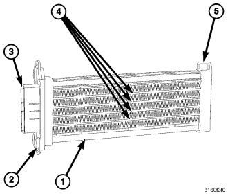
NOTE: LHD model shown. RHD model similar.
An electric positive temperature coefficient (PTC) heater unit (1) is used on vehicles when equipped with the 3.0L diesel engine. The PTC heater unit aids in passenger compartment heating by compensating for the lower engine coolant temperatures produced by the diesel engine. The PTC heater unit is mounted in the front HVAC air distribution housing, downstream of the heater core and is controlled by the diesel engine control module (ECM) and the vehicle's front control module (FCM) through three relays located in the power distribution center (PDC).
The PTC heater consists of a molded plastic mounting plate (2) with an integral wire connector receptacle (3). Concealed behind the mounting plate are four heating elements with fins (4) that transfer the heat produced by the PTC heater to the conditioned air flowing within the air distribution housing. A retaining feature (5) is molded onto the opposite end of the heater unit to support the heater unit inside the air distribution housing. The PTC heater unit is connected to the vehicle electrical system through the instrument panel wire harness and the PTC heater jumper harness.
The PTC heater unit is accessed for service by removing the instrument panel.
OPERATION
The positive temperature coefficient (PTC) heater unit dissipates 1 kW of electrical power through 4 heating bars. The engine control module (ECM) and the front control module (FCM) operate the three relays for the PTC heater unit. The PTC heater unit is split into three "banks". Each bank is driven separately based on alternator load. This allows for lower in-rush current and optimum battery charging. After a bank has been turned on, another bank can only be turned on 10 seconds after the previous. On average, the PTC banks are not switched more than 25 times for each vehicle start. Electrical power output is between 900-1050 W.
The control system for the PTC heater unit is diagnosed using a scan tool. Prior to replacing a PTC heater unit, check for any diagnostic trouble codes (DTCs) related to the ECM, FCM and heating-A/C system. Run the calibration procedure to verify that the concern is not a heating-A/C system issue (refer to 24 - HEATING & AIR CONDITIONING - DIAGNOSIS AND TESTING - HEATING AND A/C SYSTEMS and to 24 - HVAC Electrical Diagnostics for more information).
The PTC heater unit cannot be adjusted or repaired and must be replaced if found inoperative or damaged.
REMOVAL
WARNING: Refer to the applicable warnings and cautions for this system before performing the following operation (refer to 24 - HEATING & AIR CONDITIONING/PLUMBING - FRONT - WARNING) and (refer to 24 - HEATING & AIR CONDITIONING/PLUMBING - FRONT - CAUTION). Failure to follow the warnings and cautions could result in possible personal injury or death.
WARNING: Disable the airbag system before attempting any steering wheel, steering column, or instrument panel component diagnosis or service. Disconnect and isolate the negative battery (ground) cable, then wait two minutes for the airbag system capacitor to discharge before performing further diagnosis or service. This is the only sure way to disable the airbag system. Failure to take the proper precautions could result in accidental airbag deployment and possible personal injury or death.
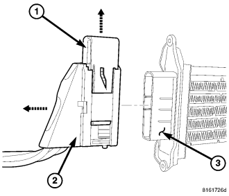
NOTE: PTC heater shown removed from distribution housing for clarity.
1. Disconnect and isolate the negative battery cable.
2. Remove the instrument panel (refer to 23 - BODY/INSTRUMENT PANEL/INSTRUMENT PANEL ASSEMBLY - REMOVAL).
NOTE: To disconnect the wire harness connector from the heater unit, pull upward on the connector lock while pulling the connector away from the heater unit.
3. Disengage the wire connector lock (1) and disconnect the wire harness connector (2) from the positive temperature coefficient (PTC) heater unit (3).
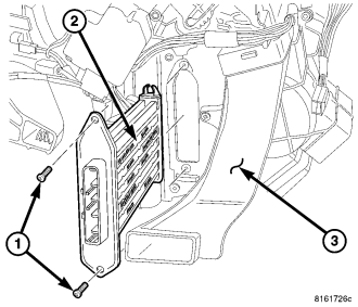
NOTE: LHD model shown. RHD model similar.
4. Remove the two screws (1) that secure the PTC heater unit (2) to the driver side of the front HVAC air distribution housing (3).
5. Carefully remove the PTC heater unit from the air distribution housing by pulling it straight out of the housing.
INSTALLATION
NOTE: LHD model shown. RHD model similar.
1. Carefully install the positive temperature coefficient (PTC) heater unit (2) into the driver side of the front HVAC air distribution housing (3). Make sure to engage the top end of the heater unit to the plastic molded pin located inside of the air distribution housing, on the passenger side of the housing.
2. Install the two screws (1) that secure the PTC heater unit to the air distribution housing. Tighten the screws to 2 N·m (17 in. lbs.).
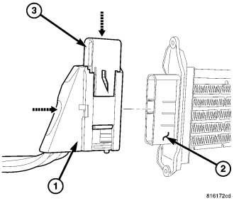
NOTE: PTC heater shown removed from distribution housing for clarity.
3. Connect the wire harness connector (1) to the PTC heater unit (2) while pulling downward on the connector lock (3). Make sure the wire harness connector and lock are fully engaged.
4. Install the instrument panel (refer to 23 - BODY/INSTRUMENT PANEL/INSTRUMENT PANEL ASSEMBLY - INSTALLATION).
5. Reconnect the negative battery cable.