DIAGNOSIS AND TESTING
- B2336-HORN CONTROL CIRCUIT LOW - FCM
- B2337-HORN CONTROL CIRCUIT HIGH - FCM
- B2339-HORN SWITCH STUCK - SCCM
B2336-HORN CONTROL CIRCUIT LOW - FCM
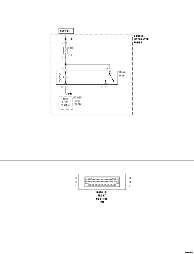
For a complete wiring diagram Refer to Section 8W.
- When Monitored:
Continuously.
- Set Condition:
If the Front Control Module (FCM) senses either excessively low or no voltage on the (X4) Horn Relay Control circuit.
| Possible Causes |
| (A43) FUSED B(+) CIRCUIT SHORTED TO GROUND |
| (X4) HORN RELAY CONTROL CIRCUIT SHORTED TO GROUND |
| (A1) / (A913) CIRCUIT OPEN TO HORN FUSE |
| (A43) FUSED B(+) CIRCUIT OPEN |
| (X4) HORN RELAY CONTROL CIRCUIT OPEN |
| HORN FUSE |
| HORN RELAY |
| INTEGRATED POWER MODULE (IPM) |
| FRONT CONTROL MODULE (FCM) |
Diagnostic Test
1. TEST FOR INTERMITTENT CONDITIONTurn the ignition on.
With the scan tool, record and erase DTCs.
Operate the Horn Switch several times.
Cycle the ignition from on to off three times and leave on.
With the scan tool, read DTCs.
Does the scan tool display: B2336 HORN CONTROL CIRCUIT LOW?
Yes
- Go To 2
No
- The conditions that caused this code to set are not present at this time. Using the wiring diagram/schematic as a guide, inspect the wiring and connectors.
- Perform BODY VERIFICATION TEST - VER 1. (Refer to 8 - ELECTRICAL/ELECTRONIC CONTROL MODULES - STANDARD PROCEDURE).
2. CHECK THE HORN FUSE
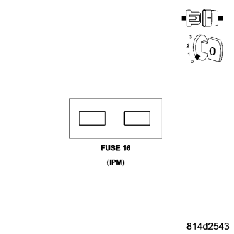
Turn the ignition off.
Remove and inspect the Horn fuse.
Is the Horn Fuse open?
Yes
- Go To 3
No
- Reinstall the Horn Fuse. Then, Go To 7.
3. CHECK FOR A SHORTED HORN RELAY
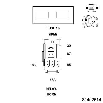
Install a known good relay in place of the Horn Relay.
Replace the Horn fuse.
Turn the ignition on.
With the scan tool, record and erase DTCs.
Operate the Horn Switch several times.
Cycle the ignition from on to off three times and leave on.
With the scan tool, read DTCs.
Does the scan tool display: B2336 HORN CONTROL CIRCUIT LOW?
Yes
- Go To 4
No
- Replace the original Horn Relay.
- Perform BODY VERIFICATION TEST - VER 1. (Refer to 8 - ELECTRICAL/ELECTRONIC CONTROL MODULES - STANDARD PROCEDURE).
4. CHECK THE (A43) FUSED B(+) CIRCUIT FOR A SHORT TO GROUND
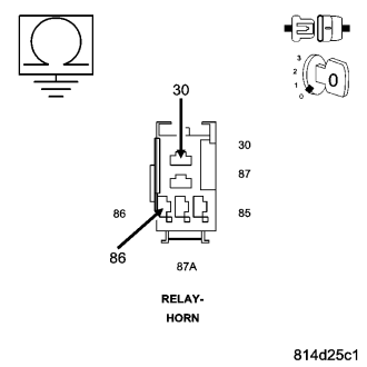
Turn the ignition off.
Remove the Horn Relay.
Remove the Horn Fuse.
Measure the resistance of the (A43) Fused B(+) circuit between ground and Cavity 86 of the Horn Relay connector in the Integrated Power Module (IPM).
Measure the resistance of the (A43) Fused B(+) circuit between ground and Cavity 30 of the Horn Relay connector in the Integrated Power Module (IPM).
Is the resistance below 10k ohms?
Yes
- Replace the Integrated Power Module (IPM) in accordance with the Service Information.
- Perform BODY VERIFICATION TEST - VER 1. (Refer to 8 - ELECTRICAL/ELECTRONIC CONTROL MODULES - STANDARD PROCEDURE).
No
- Go To 5
5. CHECK THE (X4) HORN RELAY CONTROL CIRCUIT FOR A SHORT TO GROUND
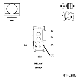
Remove the Front Control Module (FCM) in accordance with the Service Information.
Measure the resistance of the (X4) Horn Relay Control circuit between ground and Cavity 85 of the Horn Relay connector in the Integrated Power Module (IPM).
Is the resistance below 10k ohms?
Yes
- Replace the Integrated Power Module (IPM) in accordance with the Service Information.
- Perform BODY VERIFICATION TEST - VER 1. (Refer to 8 - ELECTRICAL/ELECTRONIC CONTROL MODULES - STANDARD PROCEDURE).
No
- Replace the Front Control Module (FCM) in accordance with the Service Information. Then, Go To 6.
6. CHECK FOR A SHORTED INTEGRATED POWER MODULE (IPM)
Install the original Horn Relay.
Replace the Horn fuse.
Turn the ignition on.
With the scan tool, record and erase DTCs.
Operate the Horn Switch several times.
Cycle the ignition from on to off three times and leave on.
With the scan tool, read DTCs.
Does the scan tool display: B2336 HORN CONTROL CIRCUIT LOW?
Yes
- Replace the Integrated Power Module (IPM) in accordance with the Service Information.
- Perform BODY VERIFICATION TEST - VER 1. (Refer to 8 - ELECTRICAL/ELECTRONIC CONTROL MODULES - STANDARD PROCEDURE).
No
- Perform BODY VERIFICATION TEST - VER 1. (Refer to 8 - ELECTRICAL/ELECTRONIC CONTROL MODULES - STANDARD PROCEDURE).
7. CHECK FOR POWER TO THE HORN FUSE
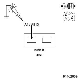
Turn the ignition on.
Using a 12-volt test light connected to ground, check for power to the Horn Fuse.
Does the test light illuminate brightly?
Yes
- Go To 8
No
- Repair the (A1) / (A913) circuit for an open.
- Perform BODY VERIFICATION TEST - VER 1. (Refer to 8 - ELECTRICAL/ELECTRONIC CONTROL MODULES - STANDARD PROCEDURE).
8. CHECK FOR AN OPEN HORN RELAY
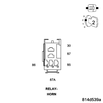
Turn the ignition off.
Install a known good relay in place of the Horn Relay.
Turn the ignition on.
With the scan tool, record and erase DTCs.
Operate the Horn Switch several times.
Cycle the ignition from on to off three times and leave on.
With the scan tool, read DTCs.
Does the scan tool display: B2336 HORN CONTROL CIRCUIT LOW?
Yes
- Go To 9
No
- Replace the original Horn Relay.
- Perform BODY VERIFICATION TEST - VER 1. (Refer to 8 - ELECTRICAL/ELECTRONIC CONTROL MODULES - STANDARD PROCEDURE).
9. CHECK THE (A43) FUSED B(+) CIRCUIT FOR AN OPEN
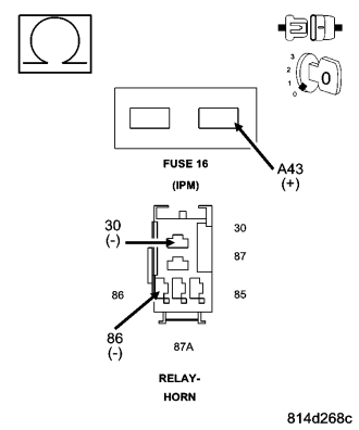
Turn the ignition off.
Remove the Horn Relay.
Remove the Horn Fuse.
Measure the resistance of the (A43) Fused B(+) circuit between the Horn Fuse (output cavity) and Cavity 86 of the Horn Relay connector in the Integrated Power Module (IPM).
Measure the resistance of the (A43) Fused B(+) circuit between the Horn Fuse (output cavity) and Cavity 30 of the Horn Relay connector in the Integrated Power Module (IPM).
Is the resistance below 5.0 ohms?
Yes
- Go To 10
No
- Replace the Integrated Power Module (IPM) in accordance with the Service Information.
- Perform BODY VERIFICATION TEST - VER 1. (Refer to 8 - ELECTRICAL/ELECTRONIC CONTROL MODULES - STANDARD PROCEDURE).
10. CHECK THE (X4) HORN RELAY CONTROL CIRCUIT FOR AN OPEN
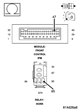
Remove the Front Control Module (FCM) in accordance with the Service Information.
Measure the resistance of the (X4) Horn Relay Control circuit between Cavity 85 of the Horn Relay connector in the Integrated Power Module (IPM) and Cavity 47 of the FCM 49-Way connector.
Is the resistance below 5.0 ohms?
Yes
- Replace the Front Control Module (FCM) in accordance with the Service Information.
- Perform BODY VERIFICATION TEST - VER 1. (Refer to 8 - ELECTRICAL/ELECTRONIC CONTROL MODULES - STANDARD PROCEDURE).
No
- Replace the Integrated Power Module (IPM) in accordance with the Service Information.
- Perform BODY VERIFICATION TEST - VER 1. (Refer to 8 - ELECTRICAL/ELECTRONIC CONTROL MODULES - STANDARD PROCEDURE).
B2337-HORN CONTROL CIRCUIT HIGH - FCM
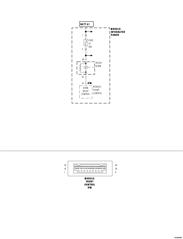
For a complete wiring diagram Refer to Section 8W.
- When Monitored:
Continuously.
- Set Condition:
If the Front Control Module (FCM) senses excessive voltage on the (X4) Horn Relay Control circuit.
| Possible Causes |
| (X4) HORN RELAY CONTROL CIRCUIT SHORTED TO VOLTAGE |
| HORN RELAY |
| INTEGRATED POWER MODULE (IPM) |
| FRONT CONTROL MODULE (FCM) |
Diagnostic Test
1. TEST FOR INTERMITTENT CONDITIONTurn the ignition on.
With the scan tool, record and erase DTCs.
Operate the Horn Switch several times.
Cycle the ignition from on to off three times and leave on.
With the scan tool, read DTCs.
Does the scan tool display: B2337 HORN CONTROL CIRCUIT HIGH?
Yes
- Go To 2
No
- The conditions that caused this code to set are not present at this time. Using the wiring diagram/schematic as a guide, inspect the wiring and connectors.
- Perform BODY VERIFICATION TEST - VER 1. (Refer to 8 - ELECTRICAL/ELECTRONIC CONTROL MODULES - STANDARD PROCEDURE).
2. CHECK FOR A SHORTED HORN RELAY
Turn the ignition off.
Install a known good relay in place of the Horn Relay.
Turn the ignition on.
With the scan tool erase DTCs.
Operate the Horn Switch several times.
Cycle the ignition from on to off three times and leave on.
With the scan tool, read DTCs.
Does the scan tool display: B2337 HORN CONTROL CIRCUIT HIGH?
Yes
- Go To 3
No
- Replace the original Horn Relay.
- Perform BODY VERIFICATION TEST - VER 1. (Refer to 8 - ELECTRICAL/ELECTRONIC CONTROL MODULES - STANDARD PROCEDURE).
3. CHECK THE (X4) HORN RELAY CONTROL CIRCUIT FOR A SHORT TO VOLTAGE
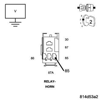
Turn the ignition off.
Remove the Horn Relay.
Remove the Front Control Module (FCM) in accordance with the Service Information.
Turn the ignition on.
Measure the voltage of the (X4) Horn Relay Control circuit.
Is the voltage above 0.2 volts?
Yes
- Replace the Integrated Power Module (IPM) in accordance with the Service Information.
- Perform BODY VERIFICATION TEST - VER 1. (Refer to 8 - ELECTRICAL/ELECTRONIC CONTROL MODULES - STANDARD PROCEDURE).
No
- Replace the Front Control Module (FCM) in accordance with the Service Information.
- Perform BODY VERIFICATION TEST - VER 1. (Refer to 8 - ELECTRICAL/ELECTRONIC CONTROL MODULES - STANDARD PROCEDURE).
B2339-HORN SWITCH STUCK - SCCM
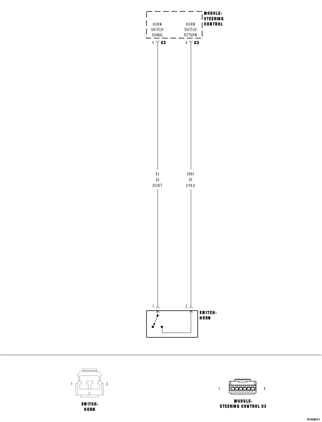
For a complete wiring diagram Refer to Section 8W.
Theory of Operation
The Horn Switch connects to the Steering Column Control Module (SCCM) via a serial sub-bus called the LIN bus. The SCCM monitors the Horn Switch status. When the switch status changes (switch is pressed or released), the SCCM processes the request and broadcasts it on the CAN B Bus where it is read and processed by the Front Control Module (FCM).
- When Monitored:
Continuously.
- Set Condition:
If the Steering Column Control Module (SCCM) senses that the Horn Switch is in the Set position for more than 50 seconds.
| Possible Causes |
| (X3) HORN SWITCH SIGNAL CIRCUIT SHORTED TO (X903) HORN SWITCH RETURN CIRCUIT |
| (X3) HORN SWITCH SIGNAL CIRCUIT SHORTED TO GROUND |
| HORN SWITCH |
| STEERING COLUMN CONTROL MODULE (SCCM) |
Diagnostic Test
1. TEST FOR INTERMITTENT CONDITIONNOTE: If DTC P0562 BATTERY VOLTAGE LOW or DTC P0563 BATTERY VOLTAGE HIGH is active along with this DTC, diagnose and repair the battery voltage related DTC first.
Turn the ignition on.
With the Scan Tool, select View DTCs in the Steering Column Control Module (SCCM).
Does the scan tool display DTC B2339 HORN SWITCH STUCK active?
Yes
- Go To 2
No
- The conditions necessary to set this DTC are not present at this time. Using the wiring diagram/schematic as a guide, inspect the wiring and connectors. In addition, wiggle test the wiring and connectors while monitoring the scan tool data relative to this circuit. Look for the data to change or for the DTC to set as active during the wiggle test. Repair as necessary.
- Perform BODY VERIFICATION TEST - VER 1. (Refer to 8 - ELECTRICAL/ELECTRONIC CONTROL MODULES - STANDARD PROCEDURE).
2. TEST THE HORN SWITCH
Turn the ignition off.
Remove the Driver Airbag in accordance with the Service information.
Disconnect the Horn Switch connector.
Measure the resistance between the (X3) Horn Switch Signal circuit and the (X903) Horn Switch Return circuit in the Horn Switch while pressing and releasing the switch several times.
Does the ohmmeter reading indicate continuity when the switch is pressed and no continuity when the switch is released?
Yes
- Go To 3
No
- Replace the Horn Switch in accordance with the Service Information.
- Perform BODY VERIFICATION TEST - VER 1. (Refer to 8 - ELECTRICAL/ELECTRONIC CONTROL MODULES - STANDARD PROCEDURE).
3. CHECK THE (X3) HORN SWITCH SIGNAL CIRCUIT FOR A SHORT TO THE (X903) HORN SWITCH RETURN CIRCUIT
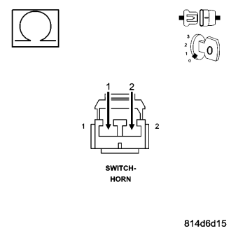
Disconnect the Steering Control Module C3 connector.
Measure the resistance between the (X3) Horn Switch Signal circuit and the (X903) Horn Switch Return circuit in the Horn Switch Connector.
Is the resistance below 10k ohms?
Yes
- Repair the (X3) Horn Switch Signal circuit for a short to the (X903) Horn Switch Return circuit.
- Perform BODY VERIFICATION TEST - VER 1. (Refer to 8 - ELECTRICAL/ELECTRONIC CONTROL MODULES - STANDARD PROCEDURE).
No
- Go To 4
4. CHECK THE (X3) HORN SWITCH SIGNAL CIRCUIT FOR A SHORT TO GROUND
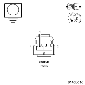
Measure the resistance between ground and the (X3) Horn Switch Signal circuit in the Horn Switch Connector.
Is the resistance below 10k ohms?
Yes
- Repair the (X3) Horn Switch Signal circuit for a short to ground.
- Perform BODY VERIFICATION TEST - VER 1. (Refer to 8 - ELECTRICAL/ELECTRONIC CONTROL MODULES - STANDARD PROCEDURE).
No
- Replace the Steering Column Control Module (SCCM) in accordance with the Service Information.
- Perform BODY VERIFICATION TEST - VER 1. (Refer to 8 - ELECTRICAL/ELECTRONIC CONTROL MODULES - STANDARD PROCEDURE).