42-SECOND ROW MODE OVERCURRENT (MTC)
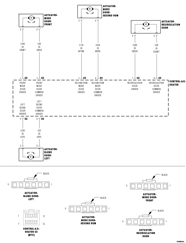
For a complete wiring diagram Refer to Section 8W.
- When Monitored:
When actuator movement is requested.
- Set Condition:
If the A/C Heater Control detects an excessive current draw on any of the door driver circuits while attempting to drive this door actuator. Note that only one overcurrent DTC can set per ignition cycle.
| Possible Causes |
| DOOR DRIVER CIRCUIT(S) SHORTED TO VOLTAGE |
| DOOR DRIVER CIRCUIT(S) SHORTED TO GROUND |
| DOOR DRIVER CIRCUITS SHORTED TOGETHER |
| FRONT MODE DOOR ACTUATOR |
| SECOND ROW MODE DOOR ACTUATOR |
| LEFT BLEND DOOR ACTUATOR |
| RECIRCULATION DOOR ACTUATOR |
| A/C HEATER CONTROL |
NOTE: This DTC must be active for the result of this test to be valid. Do not perform this test if this DTC is stored. Refer to HVAC System Test (MTC) for stored DTC test procedures.
Diagnostic Test
1. RUN THE ACTUATOR CIRCUIT TEST / DOOR CALIBRATION FUNCTION & THEN CHECK FOR ACTUATOR CIRCUIT TEST FAULTSNOTE: Diagnose and repair Actuator Circuit Test faults (DTC 61, 62, 63, 64, 65, 66, 67, 68, 69, 71, and 72) before diagnosing Overcurrent faults (DTC 41, 42, 43, and 44).
Turn the ignition on.
Actuate the Clear DTC function by performing the following:
- Turn the blower control on.
- Press the A/C mode switch down, turn the blower control to off, wait until both LEDs illuminate (approximately 5 seconds) and then release the A/C mode switch.
- When the A/C status indicator begins displaying DTCs, set the Mode switch to the floor position, simultaneously press the A/C mode switch and the EBL mode switch down until both LEDs start flashing (approximately 5 seconds) and then release the mode switches. Stored DTCs will clear from memory in approximately two seconds.
Turn the ignition off, wait 10 seconds, and turn the ignition on.
Actuate the Actuator Circuit Test / Door Calibration Function by performing the following:
- Turn the blower control off.
- Press and hold the EBL mode switch down and then turn the blower control on. Continue to hold the EBL mode switch down until the EBL status indicator begins flashing. Then, release the EBL mode switch. While the test / function is running, the EBL status indicator will flash once per second. If the test / function passes, the EBL status indicator will stop flashing. If the test / function fails, the A/C and EBL status indicators will flash alternately. Allow the test / function to run to completion before proceeding.
Actuate the Display DTC function by performing the following:
- Turn the blower control on.
- Press the A/C mode switch down, turn the blower control to off, wait until both LEDs illuminate (approximately 5 seconds) and then release the A/C mode switch.
NOTE: The A/C status indicator displays active DTCs when the EBL status indicator is not illuminated and stored DTCs when the EBL status indicator is illuminated.
Read DTCs from the A/C status indicator.
Does the A/C status indicator display any of the following DTCs: 61, 62, 63, 64, 65, 66, 67, 68, 69, 71, or 72?
Yes
- As present, diagnose and repair the Actuator Circuit Test faults in the following order: DTC 72 first, then DTC 62, then DTC 61, then DTCs 64, 66, 68, or 71, and finally DTCs 63, 65, 67, or 69. Refer to the Table Of Contents in this section for a complete list of HVAC related symptoms.
- Perform BODY VERIFICATION TEST – VER 1. (Refer to 8 - ELECTRICAL/ELECTRONIC CONTROL MODULES - STANDARD PROCEDURE).
No
- Go To2
2. CHECK THE (C266) FRONT MODE DOOR DRIVER CIRCUIT FOR A SHORT TO THE (C139) SECOND ROW MODE DOOR DRIVER CIRCUIT, (C939) SECOND ROW MODE DOOR COMMON DRIVER CIRCUIT, (C255) LEFT BLEND DOOR DRIVER CIRCUIT, (C55) LEFT BLEND DOOR COMMON DRIVER CIRCUIT, (C268) RECIRCULATION DOOR DRIVER CIRCUIT, & THE (C68) RECIRCULATION DOOR COMMON DRIVER CIRCUIT
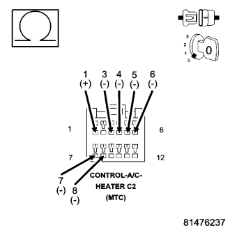
Turn the ignition off.
Disconnect the A/C Heater Control C2 harness connector.
Measure the resistance between the (C266) Front Mode Door Driver circuit and the (C139) Second Row Mode Door Driver circuit, (C939) Second Row Mode Door Common Driver circuit, (C255) Left Blend Door Driver circuit, (C55) Left Blend Door Common Driver circuit, (C268) Recirculation Door Driver circuit, and the (C68) Recirculation Door Common Driver circuit in the A/C Heater Control C2 harness connector.
Is the resistance below 10k ohms on any of the circuits?
Yes
- Repair all circuits with a resistance below 10k ohms for a short to the (C266) Front Mode Door Driver circuit.
- Perform BODY VERIFICATION TEST – VER 1. (Refer to 8 - ELECTRICAL/ELECTRONIC CONTROL MODULES - STANDARD PROCEDURE).
No
- Go To3
3. CHECK THE (C66) FRONT MODE DOOR COMMON DRIVER CIRCUIT FOR A SHORT TO THE (C139) SECOND ROW MODE DOOR DRIVER CIRCUIT, (C939) SECOND ROW MODE DOOR COMMON DRIVER CIRCUIT, (C255) LEFT BLEND DOOR DRIVER CIRCUIT, (C55) LEFT BLEND DOOR COMMON DRIVER CIRCUIT, (C268) RECIRCULATION DOOR DRIVER CIRCUIT, & THE (C68) RECIRCULATION DOOR COMMON DRIVER CIRCUIT
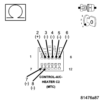
Measure the resistance between the (C66) Front Mode Door Common Driver circuit and the (C139) Second Row Mode Door Driver circuit, (C939) Second Row Mode Door Common Driver circuit, (C255) Left Blend Door Driver circuit, (C55) Left Blend Door Common Driver circuit, (C268) Recirculation Door Driver circuit, and the (C68) Recirculation Door Common Driver circuit in the A/C Heater Control C2 harness connector.
Is the resistance below 10k ohms on any of the circuits?
Yes
- Repair all circuits with a resistance below 10k ohms for a short to the (C66) Front Mode Door Common Driver circuit.
- Perform BODY VERIFICATION TEST – VER 1. (Refer to 8 - ELECTRICAL/ELECTRONIC CONTROL MODULES - STANDARD PROCEDURE).
No
- Go To4
4. CHECK THE (C139) SECOND ROW MODE DOOR DRIVER CIRCUIT FOR A SHORT TO THE (C255) LEFT BLEND DOOR DRIVER CIRCUIT, (C55) LEFT BLEND DOOR COMMON DRIVER CIRCUIT, (C268) RECIRCULATION DOOR DRIVER CIRCUIT, & THE (C68) RECIRCULATION DOOR COMMON DRIVER CIRCUIT
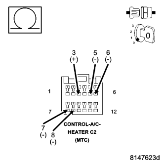
Measure the resistance between the (C139) Second Row Mode Door Driver circuit and the (C255) Left Blend Door Driver circuit, (C55) Left Blend Door Common Driver circuit, (C268) Recirculation Door Driver circuit, and the (C68) Recirculation Door Common Driver circuit in the A/C Heater Control C2 harness connector.
Is the resistance below 10k ohms on any of the circuits?
Yes
- Repair all circuits with a resistance below 10k ohms for a short to the (C139) Second Row Mode Door Driver circuit.
- Perform BODY VERIFICATION TEST – VER 1. (Refer to 8 - ELECTRICAL/ELECTRONIC CONTROL MODULES - STANDARD PROCEDURE).
No
- Go To5
5. CHECK THE (C939) SECOND ROW MODE DOOR COMMON DRIVER CIRCUIT FOR A SHORT TO THE (C255) LEFT BLEND DOOR DRIVER CIRCUIT, (C55) LEFT BLEND DOOR COMMON DRIVER CIRCUIT, (C268) RECIRCULATION DOOR DRIVER CIRCUIT, & THE (C68) RECIRCULATION DOOR COMMON DRIVER CIRCUIT
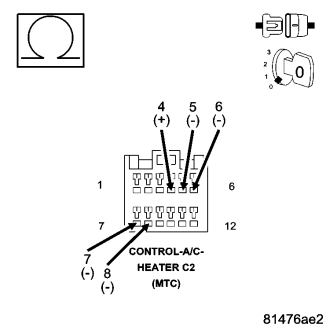
Measure the resistance between the (C939) Second Row Mode Door Common Driver circuit and (C255) Left Blend Door Driver circuit, (C55) Left Blend Door Common Driver circuit, (C268) Recirculation Door Driver circuit, and the (C68) Recirculation Door Common Driver circuit in the A/C Heater Control C2 harness connector.
Is the resistance below 10k ohms on any of the circuits?
Yes
- Repair all circuits with a resistance below 10k ohms for a short to the (C939) Second Row Mode Door Common Driver circuit.
- Perform BODY VERIFICATION TEST – VER 1. (Refer to 8 - ELECTRICAL/ELECTRONIC CONTROL MODULES - STANDARD PROCEDURE).
No
- Go To6
6. CHECK THE (C255) LEFT BLEND DOOR DRIVER CIRCUIT FOR A SHORT TO THE (C268) RECIRCULATION DOOR DRIVER CIRCUIT & THE (C68) RECIRCULATION DOOR COMMON DRIVER CIRCUIT
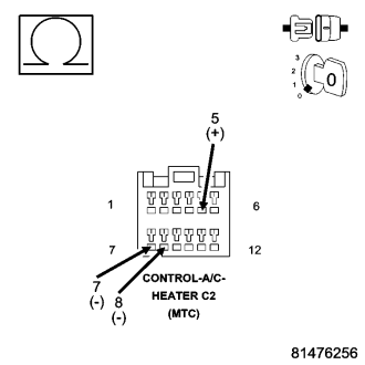
Measure the resistance between the (C255) Left Blend Door Driver circuit and the (C268) Recirculation Door Driver circuit and the (C68) Recirculation Door Common Driver circuit in the A/C Heater Control C2 harness connector.
Is the resistance below 10k ohms on any of the circuits?
Yes
- Repair all circuits with a resistance below 10k ohms for a short to the (C255) Left Blend Door Driver circuit.
- Perform BODY VERIFICATION TEST – VER 1. (Refer to 8 - ELECTRICAL/ELECTRONIC CONTROL MODULES - STANDARD PROCEDURE).
No
- Go To7
7. CHECK THE (C55) LEFT BLEND DOOR COMMON DRIVER CIRCUIT FOR A SHORT TO THE (C268) RECIRCULATION DOOR DRIVER CIRCUIT & THE (C68) RECIRCULATION DOOR COMMON DRIVER CIRCUIT
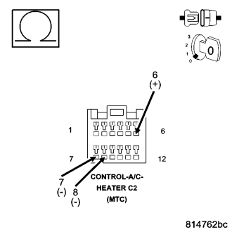
Measure the resistance between the (C55) Left Blend Door Common Driver circuit and the (C268) Recirculation Door Driver circuit and the (C68) Recirculation Door Common Driver circuit in the A/C Heater Control C2 harness connector.
Is the resistance below 10k ohms on any of the circuits?
Yes
- Repair all circuits with a resistance below 10k ohms for a short to the (C55) Left Blend Door Common Driver circuit.
- Perform BODY VERIFICATION TEST – VER 1. (Refer to 8 - ELECTRICAL/ELECTRONIC CONTROL MODULES - STANDARD PROCEDURE).
No
- Go To8
8. CHECK THE FRONT MODE DOOR ACTUATOR CIRCUIT RESISTANCE
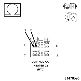
Measure the resistance between the (C66) Front Mode Door Common Driver Circuit and the (C266) Front Mode Door Driver circuit in the A/C Heater Control C2 harness connector.
Is the resistance below 30.0 ohms?
Yes
- Go To9
No
- Go To10
9. CHECK THE (C66) FRONT MODE DOOR COMMON DRIVER CIRCUIT FOR A SHORT TO THE (C266) FRONT MODE DOOR DRIVER CIRCUIT
Disconnect the Front Mode Door Actuator harness connector.
Measure the resistance between the (C66) Front Mode Door Common Driver Circuit and the (C266) Front Mode Door Driver circuit in the A/C Heater Control C2 harness connector.
Is the resistance below 10k ohms?
Yes
- Repair the (C66) Front Mode Door Common Driver Circuit for a short to the (C266) Front Mode Door Driver circuit.
- Perform BODY VERIFICATION TEST – VER 1. (Refer to 8 - ELECTRICAL/ELECTRONIC CONTROL MODULES - STANDARD PROCEDURE).
No
- Replace the Front Mode Door Actuator in accordance with the Service Information.
- Perform BODY VERIFICATION TEST – VER 1. (Refer to 8 - ELECTRICAL/ELECTRONIC CONTROL MODULES - STANDARD PROCEDURE).
10. CHECK THE SECOND ROW MODE DOOR ACTUATOR CIRCUIT RESISTANCE
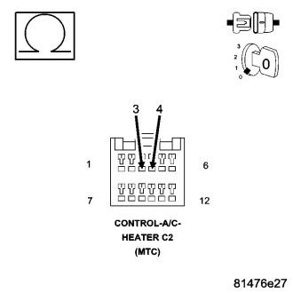
Measure the resistance between the (C939) Second Row Mode Door Common Driver Circuit and the (C139) Second Row Mode Door Driver circuit in the A/C Heater Control C2 harness connector.
Is the resistance below 30.0 ohms?
Yes
- Go To11
No
- Go To12
11. CHECK THE (C939) SECOND ROW MODE DOOR COMMON DRIVER CIRCUIT FOR A SHORT TO THE (C139) SECOND ROW MODE DOOR DRIVER CIRCUIT
Disconnect the Second Row Mode Door Actuator harness connector.
Measure the resistance between the (C939) Second Row Mode Door Common Driver Circuit and the (C139) Second Row Mode Door Driver circuit in the A/C Heater Control C2 harness connector.
Is the resistance below 10k ohms?
Yes
- Repair the (C939) Second Row Mode Door Common Driver Circuit for a short to the (C139) Second Row Mode Door Driver circuit.
- Perform BODY VERIFICATION TEST – VER 1. (Refer to 8 - ELECTRICAL/ELECTRONIC CONTROL MODULES - STANDARD PROCEDURE).
No
- Replace the Second Row Mode Door Actuator in accordance with the Service Information.
- Perform BODY VERIFICATION TEST – VER 1. (Refer to 8 - ELECTRICAL/ELECTRONIC CONTROL MODULES - STANDARD PROCEDURE).
12. CHECK THE LEFT BLEND DOOR ACTUATOR CIRCUIT RESISTANCE
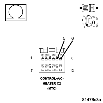
Measure the resistance between the (C55) Left Blend Door Common Driver Circuit and the (C255) Left Blend Door Driver circuit in the A/C Heater Control C2 harness connector.
Is the resistance below 30.0 ohms?
Yes
- Go To13
No
- Go To14
13. CHECK THE (C55) LEFT BLEND DOOR COMMON DRIVER CIRCUIT FOR A SHORT TO THE (C255) LEFT BLEND DOOR DRIVER CIRCUIT
Disconnect the Left Blend Door Actuator harness connector.
Measure the resistance between the (C55) Left Blend Door Common Driver Circuit and the (C255) Left Blend Door Driver circuit in the A/C Heater Control C2 harness connector.
Is the resistance below 10k ohms?
Yes
- Repair the (C55) Left Blend Door Common Driver Circuit for a short to the (C255) Left Blend Door Driver circuit.
- Perform BODY VERIFICATION TEST – VER 1. (Refer to 8 - ELECTRICAL/ELECTRONIC CONTROL MODULES - STANDARD PROCEDURE).
No
- Replace the Left Blend Door Actuator in accordance with the Service Information.
- Perform BODY VERIFICATION TEST – VER 1. (Refer to 8 - ELECTRICAL/ELECTRONIC CONTROL MODULES - STANDARD PROCEDURE).
14. CHECK THE RECIRCULATION DOOR ACTUATOR CIRCUIT RESISTANCE
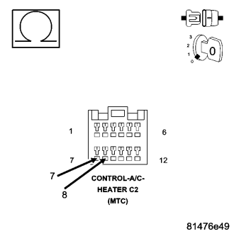
Measure the resistance between the (C68) Recirculation Door Common Driver Circuit and the (C268) Recirculation Door Driver circuit in the A/C Heater Control C2 harness connector.
Is the resistance below 30.0 ohms?
Yes
- Go To15
No
- Go To 16
15. CHECK THE (C68) RECIRCULATION DOOR COMMON DRIVER CIRCUIT FOR A SHORT TO THE (C268) RECIRCULATION DOOR DRIVER CIRCUIT
Disconnect the Recirculation Door Actuator harness connector.
Measure the resistance between the (C68) Recirculation Door Common Driver Circuit and the (C268) Recirculation Door Driver circuit in the A/C Heater Control C2 harness connector.
Is the resistance below 10k ohms?
Yes
- Repair the (C68) Recirculation Door Common Driver Circuit for a short to the (C268) Recirculation Door Driver circuit.
- Perform BODY VERIFICATION TEST – VER 1. (Refer to 8 - ELECTRICAL/ELECTRONIC CONTROL MODULES - STANDARD PROCEDURE).
No
- Replace the Recirculation Door Actuator in accordance with the Service Information.
- Perform BODY VERIFICATION TEST – VER 1. (Refer to 8 - ELECTRICAL/ELECTRONIC CONTROL MODULES - STANDARD PROCEDURE).
16. VERIFY THAT THE FAULT IS STILL PRESENT
Reconnect the A/C Heater Control C2 harness connector.
Reconnect all of the door actuator harness connectors.
Turn the ignition on.
Actuate the Clear DTC function by performing the following:
- Turn the blower control on.
- Press the A/C mode switch down, turn the blower control to off, wait until both LEDs illuminate (approximately 5 seconds) and then release the A/C mode switch.
- When the A/C status indicator begins displaying DTCs, set the Mode switch to the floor position, simultaneously press the A/C mode switch and the EBL mode switch down until both LEDs start flashing (approximately 5 seconds) and then release the mode switches. Stored DTCs will clear from memory in approximately two seconds.
Turn the ignition off, wait 10 seconds, and turn the ignition on.
Actuate the Actuator Circuit Test / Door Calibration Function by performing the following:
- Turn the blower control off.
- Press and hold the EBL mode switch down and then turn the blower control on. Continue to hold the EBL mode switch down until the EBL status indicator begins flashing. Then, release the EBL mode switch. While the test / function is running, the EBL status indicator will flash once per second. If the test / function passes, the EBL status indicator will stop flashing. If the test / function fails, the A/C and EBL status indicators will flash alternately. Allow the test / function to run to completion before proceeding.
Actuate the Display DTC function by performing the following:
- Turn the blower control on.
- Press the A/C mode switch down, turn the blower control to off, wait until both LEDs illuminate (approximately 5 seconds) and then release the A/C mode switch.
NOTE: The A/C status indicator displays active DTCs when the EBL status indicator is not illuminated and stored DTCs when the EBL status indicator is illuminated.
Read DTCs from the A/C status indicator.
Does the A/C status indicator display DTC 42?
Yes
- Replace the A/C Heater Control in accordance with the Service Information.
- Perform BODY VERIFICATION TEST – VER 1. (Refer to 8 - ELECTRICAL/ELECTRONIC CONTROL MODULES - STANDARD PROCEDURE).
No
- Using the wiring diagram as a guide, inspect the wiring and connectors for conditions causing an intermittent short that set the original fault. Repair as necessary. Then, if present, diagnose and repair all other DTCs. Refer to the Table of Contents in this Section for a complete list of HVAC related symptoms.
- Perform BODY VERIFICATION TEST – VER 1. (Refer to 8 - ELECTRICAL/ELECTRONIC CONTROL MODULES - STANDARD PROCEDURE).