*REAR A/C HEATER MODE DOOR INOPERABLE
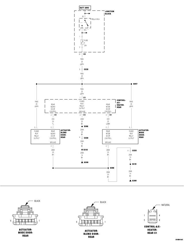
For a complete wiring diagram Refer to Section 8W.
| Possible Causes |
| (F850) FUSED RUN RELAY OUTPUT CIRCUIT OPEN OR SHORTED |
| (Z908) GROUND CIRCUIT OPEN |
| (C53) REAR MODE DOOR CONTROL CIRCUIT OPEN OR SHORTED |
| REAR MODE DOOR ACTUATOR |
| REAR A/C HEATER CONTROL |
Diagnostic Test
1. VERIFY SYMPTOMTurn the ignition on.
Set the rear blower on high.
Note location of the air exiting the rear HVAC system vents.
Operate the Rear Mode Door Control.
Did the airflow change mode (floor, bi-level and panel)?
Yes
- The rear mode door actuator is working properly. Check for an intermittent condition by inspecting the related wiring harness for chafed, pierced, pinched, and partially broken wires. Also, inspect the related connectors for broken, bent, pushed out, spread, corroded, or contaminated terminals. Repair as necessary.
No
- Go To 2
2. CHECK JB FUSE #5 (F850) FUSED RUN RELAY OUTPUT CIRCUIT
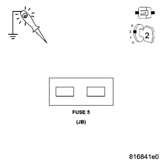
Turn the rear blower off.
Using a 12-volt test light connected to ground, check for power on both sides of JB Fuse #5.
Does the test light illuminate brightly on both sides of the fuse?
Yes
- Go To 3
No - Open Fuse
- Using the Wiring Diagram as a guide, repair the (F850) Fused Run Relay Output circuit for a short to ground. Replace the fuse.
- Perform BODY VERIFICATION TEST – VER 1. (Refer to 8 - ELECTRICAL/ELECTRONIC CONTROL MODULES - STANDARD PROCEDURE).
No - No Power to Fuse
- Using the Wiring Diagram as a guide, repair the (F850) Fused Run Relay Output circuit for an open.
- Perform BODY VERIFICATION TEST – VER 1. (Refer to 8 - ELECTRICAL/ELECTRONIC CONTROL MODULES - STANDARD PROCEDURE).
3. CHECK THE (F850) FUSED RUN RELAY OUTPUT CIRCUIT FOR AN OPEN AT THE REAR A/C HEATER CONTROL
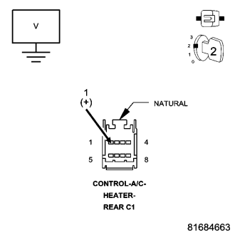
Measure the voltage of the (F850) Fused Run Relay Output circuit at the Rear A/C Heater Control C1 harness connector.
Is the voltage above 10 volts?
Yes
- Go To 4
No
- Repair the (F850) Fused Run Relay output circuit for an open.
- Perform BODY VERIFICATION TEST – VER 1. (Refer to 8 - ELECTRICAL/ELECTRONIC CONTROL MODULES - STANDARD PROCEDURE).
4. CHECK THE (Z908) GROUND CIRCUIT FOR AN OPEN AT THE REAR A/C HEATER CONTROL
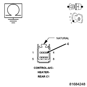
Turn the ignition off.
Disconnect the Rear A/C Heater Control C1 harness connector.
Measure the resistance between ground and the (Z908) Ground circuit at the A/C Heater Control C1 harness connector.
Is the resistance below 5.0 ohms?
Yes
- Go To 5
No
- Repair the (Z908) Ground circuit for an open.
- Perform BODY VERIFICATION TEST – VER 1. (Refer to 8 - ELECTRICAL/ELECTRONIC CONTROL MODULES - STANDARD PROCEDURE).
5. CHECK THE (F850) FUSED RUN RELAY OUTPUT CIRCUIT FOR AN OPEN AT THE REAR MODE DOOR ACTUATOR
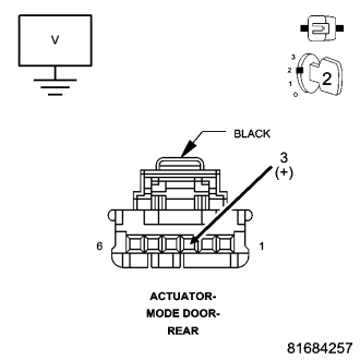
Turn the ignition on.
Measure the voltage of the (F850) Fused Run Relay Output circuit at the Rear Mode Door Actuator harness connector.
Is the voltage above 10 volts?
Yes
- Go To 6
No
- Repair the (F850) Fused Run Relay output circuit for an open.
- Perform BODY VERIFICATION TEST – VER 1. (Refer to 8 - ELECTRICAL/ELECTRONIC CONTROL MODULES - STANDARD PROCEDURE).
6. CHECK THE (Z908) GROUND CIRCUIT FOR AN OPEN AT THE REAR MODE DOOR ACTUATOR
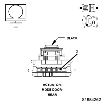
Turn the ignition off.
Disconnect the Rear Mode Door Actuator harness connector.
Measure the resistance between ground and the (Z908) Ground circuit at the Rear Mode Door Actuator harness connector.
Is the resistance below 5.0 ohms?
Yes
- Go To 7
No
- Repair the (Z908) Ground circuit for an open.
- Perform BODY VERIFICATION TEST – VER 1. (Refer to 8 - ELECTRICAL/ELECTRONIC CONTROL MODULES - STANDARD PROCEDURE).
7. CHECK THE C53 REAR MODE DOOR CONTROL CIRCUIT FUNCTION
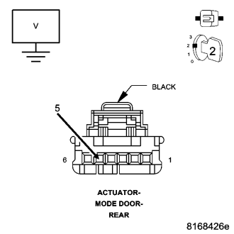
Reconnect the Rear A/C Heater Control C1 harness connector.
Turn the ignition on.
Measure the voltage of the (C53) Rear Mode Door Control circuit at the Rear Mode Door Actuator harness connector while moving the Mode Door Control on the Rear A/C Heater Control from Floor to Bi-Level to Panel.
The approximate Mode Door Control (C53) circuit voltage should be as follows:
- Below 0.5 Volts @ Hot
- 2.0 Volts ± 0.5 Volts @ Mid-Level
- Within 0.5 Volts of Battery Voltage @ Cold
Is the voltage within specifications?
Yes
- Remove the Mode Door actuator from the A/C Heater Housing Assembly. By hand, attempt to rotate the actuator in both directions. Inspect the A/C Heater Housing for damage, and for a broken or binding door. Repair as necessary in accordance with the Service Information.
- Perform BODY VERIFICATION TEST – VER 1. (Refer to 8 - ELECTRICAL/ELECTRONIC CONTROL MODULES - STANDARD PROCEDURE).
No – Voltage Remains Above 10 Volts
- Go To 8
No – Voltage Remains Below 2 Volts
- Go To 9
8. CHECK THE (C53) REAR MODE DOOR CONTROL CIRCUIT FOR A SHORT TO THE (F850) FUSED RUN RELAY OUTPUT CIRCUIT AT THE REAR MODE DOOR ACTUATOR
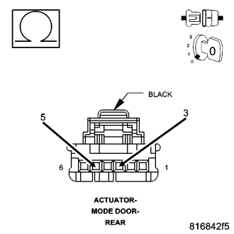
Turn ignition off.
Disconnect the Rear A/C Heater Control C1 harness connector.
Measure the resistance between the (C53) Rear Mode Door Control circuit and the (F850) Fused Run Relay Output circuit at the Rear Mode Door Actuator harness connector.
Is the resistance below 10k ohms?
Yes
- Repair the (C53) Rear Mode Door Control circuit for a short to the (F850) Fused Run Relay Output circuit.
- Perform BODY VERIFICATION TEST – VER 1. (Refer to 8 - ELECTRICAL/ELECTRONIC CONTROL MODULES - STANDARD PROCEDURE).
No
- Replace the Rear A/C Heater Control in accordance with the Service Information.
- Perform BODY VERIFICATION TEST – VER 1. (Refer to 8 - ELECTRICAL/ELECTRONIC CONTROL MODULES - STANDARD PROCEDURE).
9. CHECK THE (C53) REAR MODE DOOR CONTROL CIRCUIT FOR A SHORT TO THE (Z908) GROUND CIRCUIT AT THE REAR MODE DOOR ACTUATOR
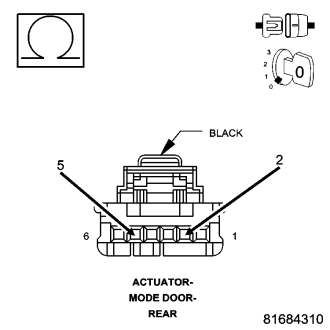
Measure the resistance between the (C53) Rear Mode Door Control circuit and the (Z908) Ground circuit at the Rear Mode Door Actuator harness connector.
Is the resistance below 10k ohms?
Yes
- Repair the (C53) Rear Mode Door Control circuit for a short to the (Z908) Ground circuit.
- Perform BODY VERIFICATION TEST – VER 1. (Refer to 8 - ELECTRICAL/ELECTRONIC CONTROL MODULES - STANDARD PROCEDURE).
No
- Go To 10
10. CHECK THE (C53) REAR MODE DOOR CONTROL CIRCUIT FOR AN OPEN BETWEEN THE REAR MODE DOOR ACTUATOR HARNESS CONNECTOR AND THE REAR A/C HEATER CONTROL HARNESS CONNECTOR
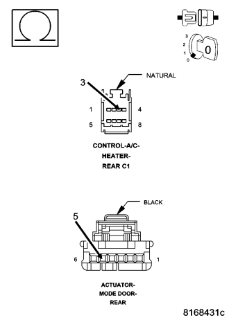
Measure the resistance of the (C53) Rear Mode Door Control circuit between the Rear Mode Door Actuator harness connector and the A/C Heater Control C1 harness connector.
Is the resistance below 5.0 ohms?
Yes
- Replace the Rear A/C Heater Control in accordance with the Service Information.
- Perform BODY VERIFICATION TEST – VER 1. (Refer to 8 - ELECTRICAL/ELECTRONIC CONTROL MODULES - STANDARD PROCEDURE).
No
- Repair the (C53) Rear Mode Door Control circuit for an open.
- Perform BODY VERIFICATION TEST – VER 1. (Refer to 8 - ELECTRICAL/ELECTRONIC CONTROL MODULES - STANDARD PROCEDURE).