B2124-IGNITION RUN CONTROL CIRCUIT OPEN
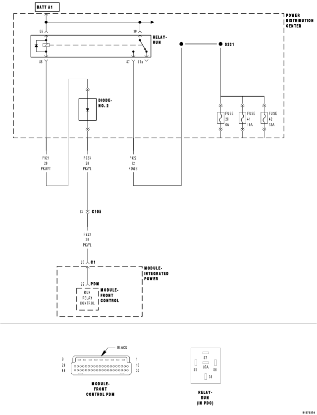
For a complete wiring diagram Refer to Section 8W.
- When Monitored:
With the ignition on.
- Set Condition:
The Front Control Module will set this DTC within 500ms if the (F921) or (F923) run relay control circuit voltage is open or shorted to ground.
| Possible Causes |
| (F921) or (F923) RUN RELAY CONTROL CIRCUIT OPEN OR SHORTED TO GROUND |
| RUN RELAY |
| FRONT CONTROL MODULE |
Diagnostic Test
1. CHECK FOR ACTIVE DTCWith the scan tool, read the active DTC's.
Cycle the ignition switch from off to on, leaving the ignition on for a minimum of 90 seconds.
With the scan tool, read the active DTC's.
Does the scan tool display this DTC as active?
Yes
- Go To 2
No
- If the DTC is stored, check for an intermittent condition. Visually inspect the related wiring harness connectors. Look for broken, bent, pushed out, or corroded terminals.
2. RUN RELAY
Turn the ignition off.
Install a substitute run relay in place of the original run relay.
Cycle the ignition switch from off to on, leaving the ignition on for a minimum of 90 seconds.
With the scan tool, read the active FCM DTC's.
Does the scan tool display this DTC as active?
Yes
- Go To 3
No
- Replace the original run relay.
- Perform BODY VERIFICATION TEST – VER 1. (Refer to BODY VERIFICATION TEST – VER 1).
3. (F921) or (F923) RUN RELAY CONTROL CIRCUIT OPEN
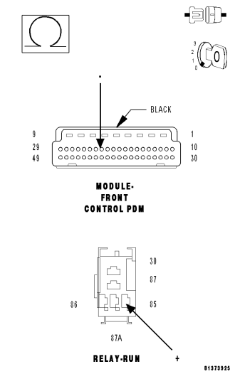
Turn the ignition off.
Remove the FCM from the Power Distribution Module.
Remove the run relay from the Rear Power Distribution Module.
NOTE: This circuit contains a diode. When checking resistance of this circuit the red ohmmeter lead must be connected to the run relay cavity (85) and the black ohmmeter lead must be connected to the FCM–PDM connector.
Measure the resistance of the Run Relay Control circuit.
Is the resistance below 10.0 ohms?
Yes
- Go To 4
No
- Repair the Run Relay Control circuit for an open.
- Perform BODY VERIFICATION TEST – VER 1. (Refer to BODY VERIFICATION TEST – VER 1).
4. (F921) RUN RELAY CONTROL CIRCUIT SHORTED TO GROUND
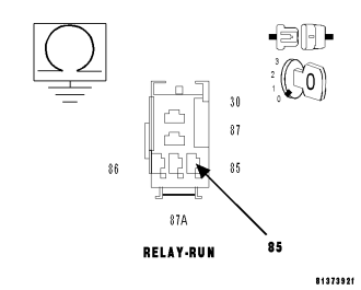
NOTE: This circuit contains a diode. When checking for a short to ground you must check both sides of the diode.
Measure the resistance between ground and the (F921) Run Relay Control circuit at the run relay cavity (85).
Is the resistance below 10.0 ohms?
Yes
- Repair the (F921) Run Relay Control circuit for a short to ground.
- Perform BODY VERIFICATION TEST – VER 1. (Refer to BODY VERIFICATION TEST – VER 1).
No
- Go To 5
5. (F923) RUN RELAY CONTROL CIRCUIT SHORTED TO GROUND
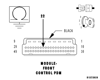
NOTE: This circuit contains a diode. When checking for a short to ground you must check both sides of the diode.
Measure the resistance between ground and the (F923) Run Relay Control circuit at the FCM–PDM connector.
Is the resistance below 10.0 ohms?
Yes
- Repair the (F923) Run Relay Control circuit for a short to ground.
- Perform BODY VERIFICATION TEST – VER 1. (Refer to BODY VERIFICATION TEST – VER 1).
No
- Inspect the wiring and connectors for damage or shorted circuits. If ok, replace and program the Front Control Module in accordance with the service information.
- Perform BODY VERIFICATION TEST – VER 1. (Refer to BODY VERIFICATION TEST – VER 1).