HAZARD SWITCH
DESCRIPTION
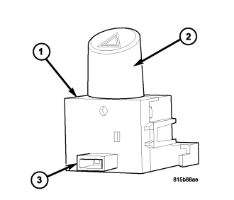
The hazard switch (1) is located on the top of the steering column, just below the steering wheel. This switch is the control for the hazard warning lighting. The only visible component of the switch is the control push button (2) that extends through the upper steering column shroud on the top of the column. The remainder of the switch including its mounting provisions and its electrical connection (3) is concealed beneath the shroud.
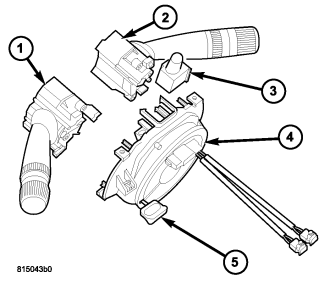
The switch housing (3) and push button are constructed of molded black plastic. A red, stencil-like International Control and Display Symbol icon for Hazard Warning identifies the hazard switch button. The switch is secured to the back of the Steering Control Module (SCM) (4) by plastic latch features integral to the SCM housing. A single integral interface connector with two terminal pins is integral to the switch housing and connects the switch directly to the SCM.
The hazard switch cannot be adjusted or repaired. If the switch is ineffective or damaged, the entire switch unit must be replaced.
OPERATION
The hazard switch features a push-push type latching push button. When the push button is in its latched (lowered) position the switch contacts are open, and when the push button is in its unlatched (raised) position the switch contacts are closed. Although the hazard switch is mounted to the SCM, the hazard switch circuits only pass through the SCM. The SCM has no control over and does not monitor the hazard switch output.
The hazard switch receives a ground on one terminal and provides a ground signal output to the Front Control Module (FCM) whenever the switch contacts are closed. The FCM responds to this input by controlling a battery voltage output and the flash rate for each of the right and left turn signal lamps, then sends an electronic hazard switch status message over the Controller Area Network (CAN) data bus to the ElectroMechanical Instrument Cluster (EMIC) (also known as the Cab Compartment Node/CCN) to control the illumination and flash rate of the right and left turn signal indicators, as well as to control the click rate of an electromechanical relay soldered onto the EMIC electronic circuit board that emulates the sound emitted by a conventional hazard warning flasher.
The hazard switch as well as the hard wired inputs and outputs of the switch may be diagnosed using conventional diagnostic tools and procedures. Refer to the appropriate wiring information.
REMOVAL
WARNING: To avoid personal injury or death, on vehicles equipped with airbags, disable the supplemental restraint system before attempting any steering wheel, steering column, airbag, seat belt tensioner, impact sensor, or instrument panel component diagnosis or service. Disconnect and isolate the battery negative (ground) cable, then wait two minutes for the system capacitor to discharge before performing further diagnosis or service. This is the only sure way to disable the supplemental restraint system. Failure to take the proper precautions could result in accidental airbag deployment.
1. Disconnect and isolate the battery negative cable.
2. Remove both the upper and lower shrouds from the steering column. (Refer to 19 - STEERING/COLUMN/SHROUD - REMOVAL).
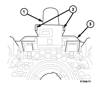
3. While spreading the plastic latch features (2) integral to the back of the Steering Control Module (SCM) (3) outward from the back of the hazard switch (1), pull the switch straight away from the back of the SCM far enough to disconnect it from the SCM.
4. Remove the switch from the SCM.
INSTALLATION
WARNING: To avoid personal injury or death, on vehicles equipped with airbags, disable the supplemental restraint system before attempting any steering wheel, steering column, airbag, seat belt tensioner, impact sensor, or instrument panel component diagnosis or service. Disconnect and isolate the battery negative (ground) cable, then wait two minutes for the system capacitor to discharge before performing further diagnosis or service. This is the only sure way to disable the supplemental restraint system. Failure to take the proper precautions could result in accidental airbag deployment.
1. Position the hazard switch (1) to the back of the Steering Control Module (SCM) (3) and align the switch connector to the receptacle in the SCM.
2. Press the switch into place until both plastic latch features (2) integral to the SCM are fully engaged on the back of the switch housing.
3. Reinstall the upper and lower shrouds onto the steering column. (Refer to 19 - STEERING/COLUMN/SHROUD - INSTALLATION).
4. Reconnect the battery negative cable.