B1948-POWER LIFTGATE PINCH SENSOR 2 CIRCUIT HIGH
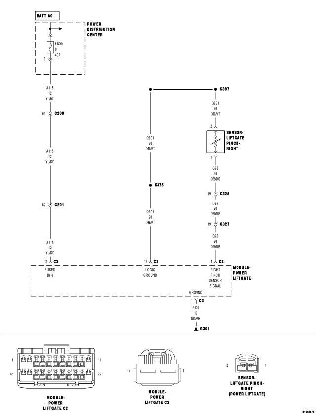
For a complete wiring diagram Refer to Section 8W
- When Monitored:
Whenever the Power Liftgate Module is awake.
- Set Condition:
The Power Liftgate Module has detected the Right Liftgate Pinch Sensor circuit voltage is above 5.2 volts for over 10 seconds.
| Possible Causes |
| (Q901) LOGIC GROUND OPEN |
| (Q78) RIGHT PINCH SENSOR SIGNAL CIRCUIT OPEN |
| (Q78) RIGHT PINCH SENSOR SIGNAL CIRCUIT SHORT TO VOLTAGE |
| RIGHT LIFTGATE PINCH SENSOR |
| POWER LIFTGATE MODULE |
| EXTREME COLD TEMPERATURE, BELOW -30°C (-22°F) |
Diagnostic Test
NOTE: The vehicle should be at room temperature when this test is performed
1. DTC PRESENTWith the scan tool, record DTCs and any liftgate inhibitors.
Erase DTCs.
Turn the ignition off, wait 10 seconds, then turn the ignition on.
Operate the liftgate several times.
With the scan tool, read DTCs.
Does the scan tool display B1948–POWER LIFTGATE PINCH SENSOR 2 CIRCUIT HIGH?
Yes
- Go To 2
No
- Using the wiring diagram/schematic as a guide, inspect the wiring and connectors for an intermittent condition.
- Perform BODY VERIFICATION TEST - VER 1. (Refer to 8 - ELECTRICAL/ELECTRONIC CONTROL MODULES - STANDARD PROCEDURE).
2. (Q901) LOGIC GROUND OPEN
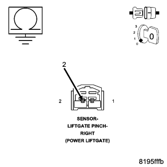
Turn the ignition off.
Disconnect the Right Liftgate Pinch Sensor connector.
Measure the resistance between ground and the (Q901) Logic Ground circuit.
Is the resistance below 9.5 ohms?
Yes
- Go To3
No
- Repair the (Q901) Logic Ground circuit for an open.
- Perform BODY VERIFICATION TEST - VER 1. (Refer to 8 - ELECTRICAL/ELECTRONIC CONTROL MODULES - STANDARD PROCEDURE).
3. (Q78) RIGHT PINCH SENSOR SIGNAL CIRCUIT OPEN
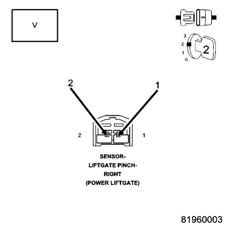
Turn the ignition on.
Measure the voltage between the (Q901) Logic Ground circuit and the (Q78) Right Pinch Sensor Signal circuit.
Is the voltage below 5.3 volts?
Yes
- Go To4
No
- Go To 5
4. CHECK THE (Q78) RIGHT PINCH SENSOR SIGNAL CIRCUIT FOR AN OPEN
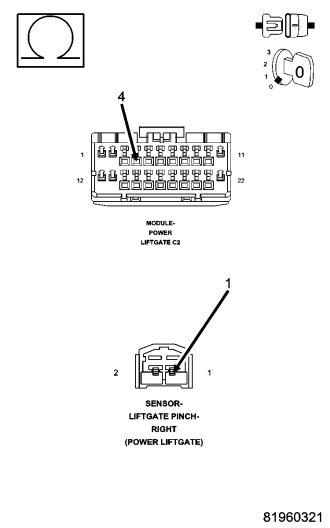
Turn the ignition off.
Disconnect the Power Liftgate Module C2 harness connector.
Measure the resistance of the (Q78) Right Pinch Sensor Signal circuit between the Power Liftgate Module C2 harness connector and the Right Liftgate Pinch Sensor harness connector.
Is the resistance below 5.0 ohms?
Yes
- Replace the Power Liftgate Module in accordance with the service information.
- Perform BODY VERIFICATION TEST - VER 1. (Refer to 8 - ELECTRICAL/ELECTRONIC CONTROL MODULES - STANDARD PROCEDURE).
No
- Repair the (Q78) Right Pinch Sensor Signal circuit for an open.
- Perform BODY VERIFICATION TEST - VER 1. (Refer to 8 - ELECTRICAL/ELECTRONIC CONTROL MODULES - STANDARD PROCEDURE).
5. (Q78) RIGHT PINCH SENSOR SIGNAL SHORT TO VOLTAGE
Measure the voltage between the (Q901) Logic Ground circuit and the (Q78) Right Pinch Sensor Signal circuit in the Right Liftgate Pinch Sensor connector.
Is the voltage above 5.2 volts?
No
- Replace the Right Liftgate Pinch Sensor in accordance with the service information.
- Perform BODY VERIFICATION TEST - VER 1. (Refer to 8 - ELECTRICAL/ELECTRONIC CONTROL MODULES - STANDARD PROCEDURE).
Yes
- Repair the (Q78) Right Pinch Sensor Signal circuit for a short to voltage. If the (Q78) Right Pinch Sensor Signal circuit is OK, replace the Power Liftgate Module in accordance with the service information.
- Perform BODY VERIFICATION TEST - VER 1. (Refer to 8 - ELECTRICAL/ELECTRONIC CONTROL MODULES - STANDARD PROCEDURE).