B1961-POWER LIFTGATE CHIME CONTROL CIRCUIT HIGH
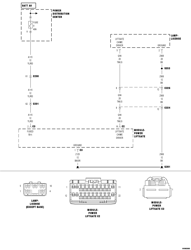
For a complete wiring diagram Refer to Section 8W
- When Monitored:
Whenever the Power Liftgate Module is awake.
- Set Condition:
The power liftgate module has detected the chime circuit voltage is over four volts during operation or over 1.5 volts when not operating.
| Possible Causes |
| (Q94) LIFTGATE CHIME DRIVER CIRCUIT SHORT TO VOLTAGE |
| (Q94) LIFTGATE CHIME DRIVER CIRCUIT OPEN |
| GROUND CIRCUIT OPEN |
| LICENSE LAMP/POWER LIFTGATE CHIME ASSEMBLY |
| POWER LIFTGATE MODULE |
Diagnostic Test
1. DTC PRESENTWith the scan tool, record DTCs.
Erase DTCs.
Turn the ignition off, wait 10 seconds, then turn the ignition on.
Operate the liftgate several times.
With the scan tool, read DTCs.
Does the scan tool display B1961–POWER LIFTGATE CHIME CONTROL CIRCUIT HIGH?
Yes
- Go To 2
No
- Using the wiring diagram/schematic as a guide, inspect the wiring and connectors for an intermittent condition.
- Perform BODY VERIFICATION TEST - VER 1. (Refer to 8 - ELECTRICAL/ELECTRONIC CONTROL MODULES - STANDARD PROCEDURE).
2. (Q94) LIFTGATE CHIME DRIVER CIRCUIT SHORT TO VOLTAGE
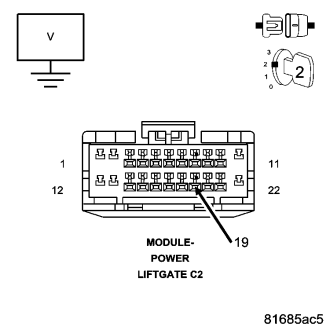
Turn the ignition off.
Disconnect the Power Liftgate Module C2 harness connector.
Turn the ignition on.
Measure the voltage between ground and the (Q94) Liftgate Chime Driver circuit.
Is there any voltage present?
No
- Go To 3
Yes
- Repair the (Q94) Liftgate Chime Driver circuit for a short to voltage.
- Perform BODY VERIFICATION TEST - VER 1. (Refer to 8 - ELECTRICAL/ELECTRONIC CONTROL MODULES - STANDARD PROCEDURE).
3. (Q94) LIFTGATE CHIME DRIVER CIRCUIT OPEN
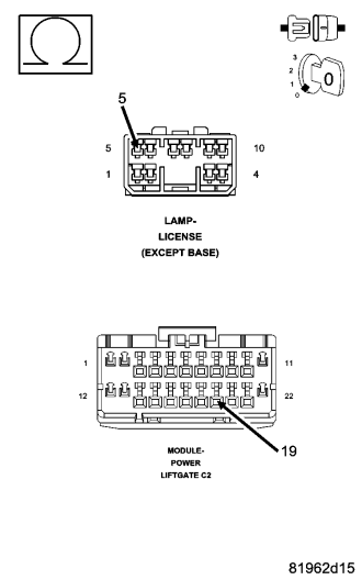
Turn the ignition off.
Disconnect the Power Liftgate Chime harness connector.
Measure the resistance of the (Q94) Liftgate Chime Driver circuit between the Power Liftgate Module C2 harness connector and the License Plate Lamp/Power Liftgate Chime connector.
Is the resistance below 5.0 ohms?
Yes
- Go To 4
No
- Repair the (Q94) Liftgate Chime Driver circuit for an open.
- Perform BODY VERIFICATION TEST - VER 1. (Refer to 8 - ELECTRICAL/ELECTRONIC CONTROL MODULES - STANDARD PROCEDURE).
4. (Z800) GROUND CIRCUIT OPEN
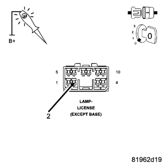
NOTE: The test light must illuminate brightly. Compare the brightness to that of a direct connection to the battery.
Using a 12-volt test light connected to 12-volts, check the (Z800) Ground circuit.
Does the test tight illuminate brightly?
Yes
- Go To 5
No
- Repair the (Z800) Ground circuit for an open.
- Perform BODY VERIFICATION TEST - VER 1. (Refer to 8 - ELECTRICAL/ELECTRONIC CONTROL MODULES - STANDARD PROCEDURE).
5. CHECK THE POWER LIFTGATE CHIME
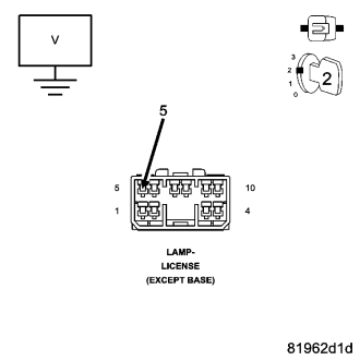
Reconnect the Power Liftgate Module C2 harness connector.
Turn the ignition on.
While using the scan tool to actuate the Power Liftgate Chime, measure the voltage of the (Q94) Power Liftgate Chime Driver circuit.
Does the voltage cycle between 0 and 12 volts?
No
- Replace the Power Liftgate Module in accordance with service information.
- Perform BODY VERIFICATION TEST - VER 1. (Refer to 8 - ELECTRICAL/ELECTRONIC CONTROL MODULES - STANDARD PROCEDURE).
Yes
- Replace the Power Liftgate Chime in accordance with the service information.
- Perform BODY VERIFICATION TEST - VER 1. (Refer to 8 - ELECTRICAL/ELECTRONIC CONTROL MODULES - STANDARD PROCEDURE).