B196D-POWER LIFTGATE OPEN DIRECTION - FULL OPEN SWITCH PERFORMANCE
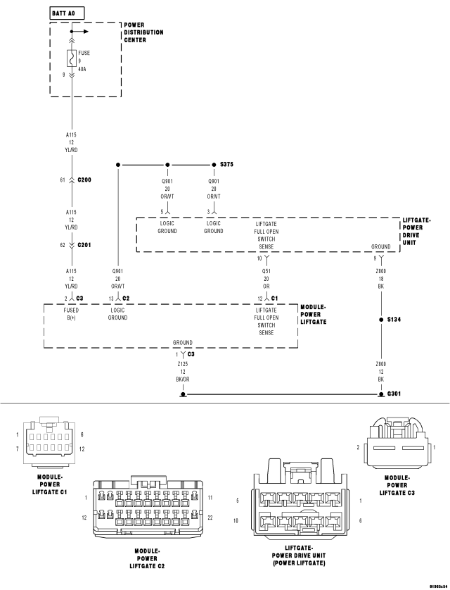
For a complete wiring diagram Refer to Section 8W
- When Monitored:
During the Power Liftgate open cycle or liftgate fully closed prior to activation.
- Set Condition:
The Power Liftgate Drive Unit Full Open Switch was detected as closed with the liftgate being fully closed or the latch being fully latched.
The Power Liftgate Drive Unit Full Open Switch was detected as closed before 820 pulses of the Power Liftgate Drive Unit position sensor were counted since the start of the open operation.
The Power Liftgate Drive Unit Full Open Switch remained open after approximately 860 pulses of the Power Liftgate Drive Unit position sensor were counted since the start of the open operation.
May be triggered by an intermittent full open switch failure.
| Possible Causes |
| LATCH HAS BEEN MANUALLY LATCHED WITH THE GATE IN THE FULL OPEN POSITION |
| (Q51) LIFTGATE FULL OPEN SWITCH SENSE CIRCUIT OPEN |
| (Q51) LIFTGATE FULL OPEN SWITCH SENSE CIRCUIT INTERMITTENT SHORT TO GROUND |
| (Q51) LIFTGATE FULL OPEN SWITCH SENSE CIRCUIT SHORT TO GROUND |
| (Q901) LOGIC GROUND OPEN |
| POWER LIFTGATE DRIVE UNIT |
| POWER LIFTGATE MODULE |
Diagnostic Test
1. DTC PRESENTWith the scan tool, record and erase DTCs.
Turn the ignition off, wait 10 seconds, then turn the ignition on.
Operate the power liftgate several times if possible.
Refer to service information and perform the Power Liftgate Learn Cycle procedure
With the scan tool, read ACTIVE DTCs.
Does the scan tool display B196D–POWER LIFTGATE OPEN DIRECTION – FULL OPEN SWITCH PERFORMANCE?
Yes
- Go To2
No
- Using the wiring diagram/schematic as a guide, inspect the wiring and connectors for an intermittent condition. Operate the liftgate several times and check for any binding or obstructions.
- Perform BODY VERIFICATION TEST - VER 1. (Refer to 8 - ELECTRICAL/ELECTRONIC CONTROL MODULES - STANDARD PROCEDURE).
2. OBSTRUCTION OR STICKING SWITCH
Examine the liftgate for proper fit and alignment, foreign material in the drive unit or anything that would cause an obstruction to proper operation of the Full Open Switch.
With the scan tool under PLGM, read the FULL OPEN SWITCH state.
Manually operate the liftgate while monitoring the scan tool.
Does the switch status change smoothly as the liftgate is pulled down from the full open position?
Yes
- Go To3
No
- Go To4
3. (Q51) FULL OPEN SWITCH SENSE CIRCUIT INTERMITTENT SHORT TO GROUND
CAUTION: Never operate the Power Liftgate Drive Unit with the link rod removed as it could damage the Drive Unit.
Gain access to the Power Liftgate Drive Unit harness connector.
Gain access to the Power Liftgate Module.
With the scan tool in Inputs/Outputs, read the FULL OPEN SWITCH state.
Ensure the link rod is connected at this time.
Manually open the liftgate to mid position.
While monitoring the scan tool, wiggle the wiring harness from the Power Liftgate Module to the Full Open Switch on the Power Liftgate Drive Unit assembly.
Did the switch status ever change?
Yes
- Repair the (Q51) Liftgate Full Open Switch Sense circuit for an intermittent short to ground.
- Perform BODY VERIFICATION TEST - VER 1. (Refer to 8 - ELECTRICAL/ELECTRONIC CONTROL MODULES - STANDARD PROCEDURE).
No
- Replace the Power Liftgate Drive Unit in accordance with the service information.
- Perform BODY VERIFICATION TEST - VER 1. (Refer to 8 - ELECTRICAL/ELECTRONIC CONTROL MODULES - STANDARD PROCEDURE).
4. POWER LIFTGATE DRIVE UNIT – FULL OPEN SWITCH
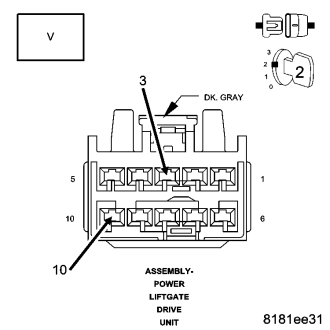
Disconnect the Power Liftgate Drive Unit harness connector.
Measure the voltage between the (Q51) Liftgate Full Open Switch Sense circuit and (Q901) Logic Ground in the Drive Unit harness connector.
While measuring the voltage, wiggle the harness from the Power Liftgate module to the Power Liftgate Drive Unit harness connector.
Is the voltage constantly above 4.6 volts?
Yes
- Replace the Power Liftgate Drive Unit in accordance with the service information.
- Perform BODY VERIFICATION TEST - VER 1. (Refer to 8 - ELECTRICAL/ELECTRONIC CONTROL MODULES - STANDARD PROCEDURE).
No
- Go To6
5. (Q51) LIFTGATE FULL OPEN SWITCH SENSE CIRCUIT SHORT TO GROUND
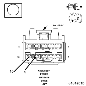
Turn the ignition off.
Disconnect the Power Liftgate Module C1 harness connector.
Measure the resistance between the (Z800) Ground and the (Q51) Liftgate Full Open Switch sense circuit in the Power Liftgate Drive Unit harness connector.
Is the resistance below 1000.0 ohms?
Yes
- Repair the (Q51) Liftgate Full Open Switch Sense circuit for a short to ground.
- Perform BODY VERIFICATION TEST - VER 1. (Refer to 8 - ELECTRICAL/ELECTRONIC CONTROL MODULES - STANDARD PROCEDURE).
No
- Go To 6
6. (Q51) LIFTGATE FULL OPEN SWITCH SENSE CIRCUIT SHORT TO (Q901) LOGIC GROUND
Measure the resistance between the (Q51) Liftgate Full Open Switch sense circuit and the (Q901) Logic Ground circuit in the Power Liftgate Drive Unit harness connector.
Is the resistance below 1000.0 ohms?
Yes
- Repair the (Q51) Liftgate Full Open Switch Sense circuit for a short to ground.
- Perform BODY VERIFICATION TEST - VER 1. (Refer to 8 - ELECTRICAL/ELECTRONIC CONTROL MODULES - STANDARD PROCEDURE).
No
- Go To 7
7. (Q901) LOGIC GROUND OPEN
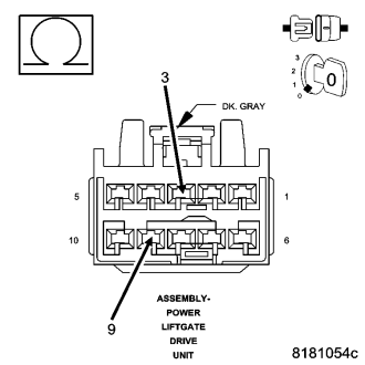
Turn the ignition off.
Disconnect the Power Liftgate Drive Unit connector.
Measure the resistance between the (Z800) Ground and the (Q901) Logic Ground circuit in the Power Liftgate Drive Unit connector.
Is the resistance below 9.5 ohms?
Yes
- Go To 8
No
NOTE: The (Q901) Logic Ground circuit is grounded through the Power Liftgate Module and the (Z800) Ground circuit.
Repair the (Q901) Logic Ground circuit for an open.- Perform BODY VERIFICATION TEST - VER 1. (Refer to 8 - ELECTRICAL/ELECTRONIC CONTROL MODULES - STANDARD PROCEDURE).
8. (Q51) LIFTGATE FULL OPEN SWITCH SENSE CIRCUIT OPEN
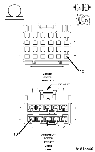
Measure the resistance of the (Q51) Liftgate Full Open Switch Sense circuit between the Power Liftgate C1 harness connector and the Power Liftgate Drive Unit harness connector.
Wiggle the wiring Power Liftgate Module harness to check for an intermittent open condition.
Is the resistance below 5.0 ohms?
No
- Repair the (Q51) Liftgate Full Open Switch Sense circuit for an open.
- Perform BODY VERIFICATION TEST - VER 1. (Refer to 8 - ELECTRICAL/ELECTRONIC CONTROL MODULES - STANDARD PROCEDURE).
Yes
- Replace the Power Liftgate Module in accordance with the service information.
- Perform BODY VERIFICATION TEST - VER 1. (Refer to 8 - ELECTRICAL/ELECTRONIC CONTROL MODULES - STANDARD PROCEDURE).