B197D-POWER LIFTGATE LATCH CINCH - PAWL SWITCH PERFORMANCE
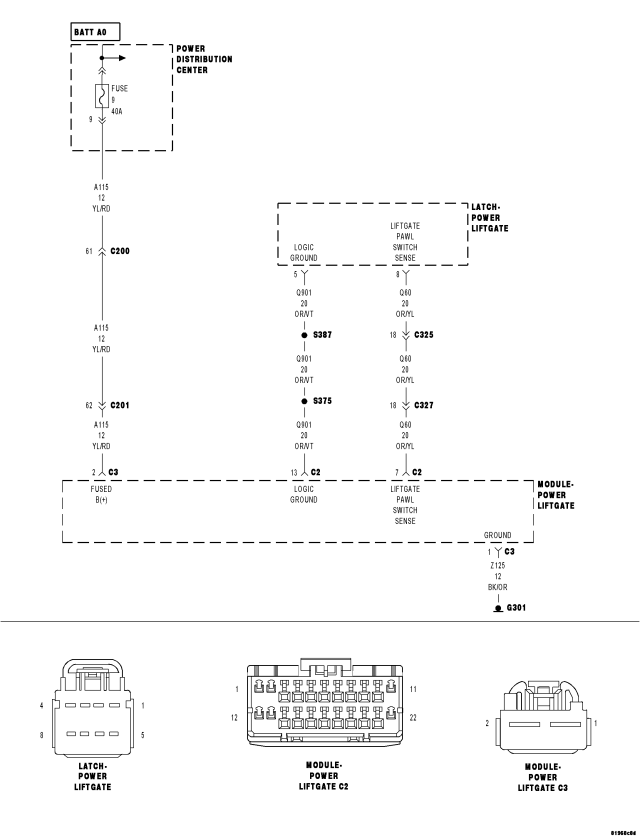
For a complete wiring diagram Refer to Section 8W
- When Monitored:
Whenever the power liftgate is performing a cinching operation.
- Set Condition:
The pawl switch did not transition from closed to open during the cinching operation.
| Possible Causes |
| BINDING LIFTGATE |
| MISALIGNED LIFTGATE WEATHERSTRIP |
| (Q901) LOGIC GROUND CIRCUIT OPEN |
| (Q60) LIFTGATE PAWL SWITCH SENSE CIRCUIT OPEN |
| (Q60) LIFTGATE PAWL SWITCH SENSE CIRCUIT SHORT TO GROUND |
| (Q60) LIFTGATE PAWL SWITCH SENSE CIRCUIT SHORT TO VOLTAGE |
| POWER LIFTGATE LATCH |
Diagnostic Test
1. DTC PRESENTNOTE: This DTC will only set after the cinching operation. This may make it difficult to reproduce.
With the scan tool, record and erase DTC's.
Turn the ignition off, wait 10 seconds, then turn the ignition on.
Operate the power liftgate several times if possible.
With the scan tool, read ACTIVE DTCs.
Does the scan tool display B197D–POWER LIFTGATE LATCH CINCH - PAWL SWITCH PERFORMANCE?
Yes
- Go To2
No
- Using the wiring diagram/schematic as a guide, inspect the wiring and connectors for an intermittent condition. Operate the door several times and check for any binding or other obstructions.
- Perform BODY VERIFICATION TEST - VER 1. (Refer to 8 - ELECTRICAL/ELECTRONIC CONTROL MODULES - STANDARD PROCEDURE).
2. BINDING LIFTGATE
Examine the liftgate for proper fit and alignment, loose/hard or torn seals, misaligned latch striker or anything that would cause an obstruction to proper operation.
Manually operate the liftgate of a known good vehicle and notice the effort needed to open and close. Pay particular attention to the cinch and latch operations.
Compare the effort needed on the disabled liftgate.
Does it take more effort to operate the liftgate than it should?
Yes
- Refer to Service information for the related symptom(s).
- Perform BODY VERIFICATION TEST - VER 1. (Refer to 8 - ELECTRICAL/ELECTRONIC CONTROL MODULES - STANDARD PROCEDURE).
No
- Go To3
3. (Q901) LOGIC GROUND CIRCUIT OPEN
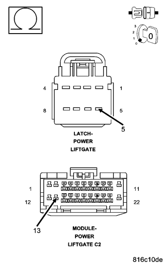
Turn the ignition off.
Disconnect the Power Liftgate Module C2 harness connector.
Disconnect the Power Liftgate Latch harness connector.
Measure the resistance of the (Q901) Logic Ground circuit between the Power Liftgate Module C2 harness connector and the Power Liftgate Latch harness connector.
Wiggle the harness while observing the ohmmeter.
Is the resistance below 2.0 ohms?
Yes
- Go To4
No
- Repair the (Q901) Sensor Ground circuit for an open.
- Perform BODY VERIFICATION TEST - VER 1. (Refer to 8 - ELECTRICAL/ELECTRONIC CONTROL MODULES - STANDARD PROCEDURE).
4. (Q60) LIFTGATE PAWL SWITCH SENSE CIRCUIT OPEN
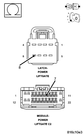
Measure the resistance of the (Q60) Liftgate Pawl Switch Sense circuit between the Power Liftgate Module C2 harness connector and the Power Liftgate Latch harness connector.
Wiggle the harness while observing the ohmmeter.
Is the resistance below 2.0 ohms?
Yes
- Go To7
No
- Repair the (Q60) Liftgate Pawl Switch Sense circuit for an open.
- Perform BODY VERIFICATION TEST - VER 1. (Refer to 8 - ELECTRICAL/ELECTRONIC CONTROL MODULES - STANDARD PROCEDURE).
5. (Q60) LIFTGATE PAWL SWITCH SENSE CIRCUIT SHORT TO THE (Q901) LOGIC GROUND CIRCUIT
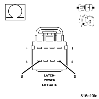
Reconnect all Power Liftgate Module harness connectors before proceeding.
Measure the resistance between the (Q901) Logic Ground and the (Q60) Liftgate Pawl Switch Sense circuit.
Wiggle the harness while observing the ohmmeter.
Is the resistance below 1000.0 ohms?
Yes
- Repair the (Q60) Liftgate Pawl Switch Sense circuit for a short to the (Q901) Logic Ground circuit.
- Perform BODY VERIFICATION TEST - VER 1. (Refer to 8 - ELECTRICAL/ELECTRONIC CONTROL MODULES - STANDARD PROCEDURE).
No
- Go To6
6. (Q60) LIFTGATE PAWL SWITCH SENSE CIRCUIT SHORT TO VOLTAGE
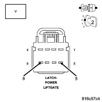
Disconnect the Power Liftgate Latch harness connector.
Measure the voltage between the (Q901) Logic Ground circuit and the (Q60) Liftgate Pawl Switch Sense circuit.
Wiggle the harness while observing the voltmeter.
Is there any voltage present?
No
- Go To 7
Yes
- Repair the (Q60) Liftgate Pawl Switch Sense circuit for a short to voltage.
- Perform BODY VERIFICATION TEST - VER 1. (Refer to 8 - ELECTRICAL/ELECTRONIC CONTROL MODULES - STANDARD PROCEDURE).
7. (Q60) LIFTGATE PAWL SWITCH SENSE CIRCUIT SHORT TO GROUND
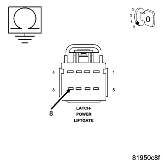
Reconnect all Power Liftgate Module harness connectors before proceeding.
Measure the resistance between Ground and the (Q60) Liftgate Pawl Switch Sense circuit in the Power Liftgate Latch harness connector.
Wiggle the harness while observing the ohmmeter.
Is the resistance below 1000.0 ohms?
Yes
- Repair the (Q60) Liftgate Pawl Switch Sense circuit for a short to the (Q901) Logic Ground circuit.
- Perform BODY VERIFICATION TEST - VER 1. (Refer to 8 - ELECTRICAL/ELECTRONIC CONTROL MODULES - STANDARD PROCEDURE).
No
- Go To 8
8. POWER LIFTGATE MODULE
With the scan tool under PLGM, monitor the PAWL SWITCH STATUS.
Using a screwdriver, click the latch to the first detent while observing the scan tool.
Unlatch the latch by pressing the handle switch and observe the scan tool for a change of state.
Repeat this step several times while moving the liftgate in different positions and wiggling the harness to check for an intermittent open circuit.
Did the scan tool show the switch state changing correctly every time?
Yes
- Replace the Power Liftgate Latch in accordance with the service information.
- Perform BODY VERIFICATION TEST - VER 1. (Refer to 8 - ELECTRICAL/ELECTRONIC CONTROL MODULES - STANDARD PROCEDURE).
No
- Check the Power Liftgate Module and Power Liftgate Latch harness and connectors for damage, and repair as necessary. If the Power Liftgate Module and Power Liftgate Latch harness and connectors are OK, replace the Power Liftgate Module in accordance with the service information.
- Perform BODY VERIFICATION TEST - VER 1. (Refer to 8 - ELECTRICAL/ELECTRONIC CONTROL MODULES - STANDARD PROCEDURE).