MODULE - POWER LIFTGATE CONTROL
DESCRIPTION
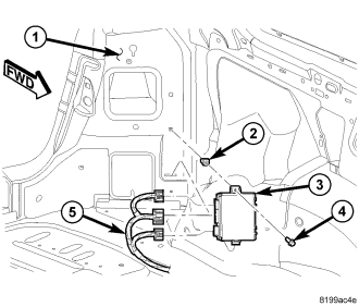
Vehicles equipped with a power liftgate system utilize a power liftgate control module (3). This module is located on the left side of the vehicle at the bottom of the D-pillar below the quarter glass. The power liftgate control module receives and monitors logic inputs from all the power liftgate system switches. This module also contains the software technology to detect liftgate obstructions and stop or reverse the door accordingly.
OPERATION
The power liftgate control module contains the electronic circuitry and software used to control the sequence of events for the power liftgate system. This module communicates on the Controller Area Network (CAN) to monitor many different inputs and outputs such as door lock status, transmission gear selector position and vehicle speed.
The power liftgate open/close command can be initiated by either one press of the power liftgate overhead console switch or two presses of the key fob power liftgate switch. The overhead switch is hardwired to the power liftgate control module. The key fob, sends a signal out on the Controller Area Network (CAN) Data Bus circuit. This signal is detected at the power liftgate control module. The power liftgate control module then interprets the information to confirm safety requirements are met before applying power to the power liftgate drive unit to start a power cycle.
During a power liftgate open or close cycle, if the power liftgate control module detects sufficient resistance to liftgate travel, such as an obstruction in the liftgate's path. The control module will immediately stop liftgate movement and reverse the direction of travel to the full open or closed position.
The power liftgate control module has the ability to relearn. After 8 miles have been recorded on the odometer, anytime the liftgate is fully opened and fully closed using the automatic system, the module will learn from its cycle. If a replacement power liftgate component is installed or a liftgate adjustment is made, the module will relearn the effort and time required to open or close the liftgate. This learn cycle can be performed with a Diagnostic Scan Tool or with a complete cycle of the liftgate, using either one of the command switches. (Refer to 8 - ELECTRICAL/POWER LIFTGATE - STANDARD PROCEDURE - LEARN CYCLE) for detailed instructions.
REMOVAL
1. Disconnect and isolate the battery negative cable.
2. Remove the left quarter trim panel from the vehicle, (Refer to 23 - BODY/INTERIOR/QUARTER PANEL TRIM - REMOVAL).
3. Disconnect the wire harness connectors (5) from the power liftgate control module (3).
4. Remove the power liftgate control module (3) retaining screw (4).
5. Tilt the top of the module (3) away from the quarter panel (1) and lift upward to disengage the mounting tab from the locating slot.
6. Remove the power liftgate control module (3) from the vehicle.
INSTALLATION
1. Position the power liftgate control module (3) into the vehicle.
2. Insert the mounting tab into the locating slot on the quarter panel (1).
3. Install the power liftgate control module (3) retaining screw (4).
4. Connect the wire harness connectors (5) to the power liftgate control module (3).
5. Install the left quarter trim panel, (Refer to 23 - BODY/INTERIOR/QUARTER PANEL TRIM - INSTALLATION).
6. Connect the battery negative cable.
7. Using an appropriate scan tool, check and erase any power liftgate control module diagnostic trouble codes.
8. Perform the power liftgate learn cycle, (Refer to 8 - ELECTRICAL/POWER DOORS - STANDARD PROCEDURE - POWER LIFTGATE LEARN CYCLE).
9. Verify power liftgate system operation.