SENSOR - PINCH
DESCRIPTION
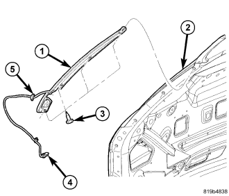
Vehicles equipped with a power liftgate system utilize two pinch sensors (1). One pinch sensor is located on each side of the liftgate (2). These sensors look like weather-strips, however they consist of pieces of electrically conductive rubber (tapeswitch), wires (4), resistor, double sided tape, and a plastic carrier. Pinch sensors are used to provide additional protection against vehicle damage or personal injury caused by an obstacle being “pinched” between the liftgate and the liftgate opening of the vehicle.
The pinch sensors are wired in series with the power liftgate control module. If one pinch sensor becomes defective the module will act as though both sensors are defective. The power liftgate latch “Cinching” operation will be disabled if a problem is detected by the control module.
OPERATION
During a power liftgate “close” cycle, if either of the two conductive rubber strips (tapeswitch) of the pinch sensor come in contact with an obstacle, the pinch sensor circuit is completed. This tells the power liftgate control module that an obstruction is felt. The control module will stop the liftgate immediately and return it to the full open position.
REMOVAL
1. Open the liftgate.
2. Disconnect and isolate the battery negative cable.
3. Remove the liftgate lower trim panel, (Refer to 23 - BODY/DECKLID/HATCH/LIFTGATE/TAILGATE/TRIM PANEL - REMOVAL).
4. Disconnect the pinch sensor wire harness connector (4).
5. Remove the screws (3) holding the pinch sensor (1) to liftgate (2).
6. Feed the pinch sensor wire harness (5) out of the liftgate (2) and remove the sensor from the vehicle.
INSTALLATION
WARNING: Use extreme caution when testing pinch sensor operation.
1. Route the pinch sensor wire harness through the hole in the liftgate. Push the wire harness grommet (5) into place until fully seated.
2. Position the pinch sensor (1) onto the liftgate (2) and install the retaining screws (3). Working from the bottom of the liftgate up, install the second screw first and then the third and fourth. Finish by installing the bottom screw last. Tighten all screws to 2 N·m (25 in. lbs.).
3. Connect the pinch sensor wire harness connector (4).
4. Install the liftgate lower trim panel, (Refer to 23 - BODY/DECKLID/HATCH/LIFTGATE/TAILGATE/TRIM PANEL - INSTALLATION).
5. Connect the battery negative cable.
6. Using an appropriate scan tool, check and erase any power liftgate control module diagnostic trouble codes related to the pinch sensor.
7. Verify power liftgate system and pinch sensor operation. Cycle the power liftgate through one complete open and close cycle, during the final close cycle press the pinch sensor to verify the power liftgate detects an obstruction and returns to the full open position.