B1D83-SEAT REAR VERTICAL MOTOR CONTROL CIRCUIT PERFORMANCE
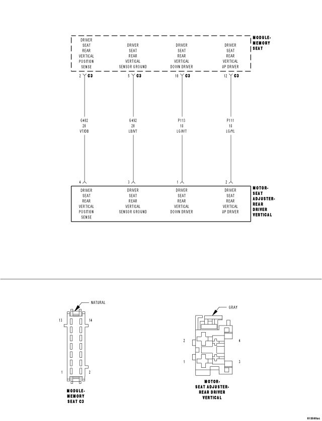
For a complete wiring diagram Refer to Section 8W.
- When Monitored:
Whenever the seat motor is activated.
- Set Condition:
If the Memory Seat Module does not detect the rotation of the seat motor this DTC will set. This DTC will only set when the seat switch is moved in the same direction three consecutive times.
| Possible Causes |
| SEAT POSITION SENSOR CIRCUIT DIAGNOSTIC TROUBLE CODES |
| (G402) DRIVER SEAT REAR VERTICAL POSITION SENSE CIRCUIT OPEN |
| (G492) DRIVER SEAT REAR VERTICAL SENSOR GROUND CIRCUIT OPEN |
| (P111) DRIVER SEAT REAR VERTICAL UP DRIVER |
| (P113) DRIVER SEAT REAR VERTICAL DOWN DRIVER |
| REAR DRIVER VERTICAL SEAT ADJUSTER MOTOR |
| MEMORY SEAT MODULE |
Diagnostic Test
1. CHECK FOR RELATED DIAGNOSTIC TROUBLE CODESTurn the ignition on.
With the scan tool, read DTC's.
Does the scan tool display any seat position sensor DTC's?
Yes
- Diagnose and repair other DTC(s) first. Refer to the Table of Contents in this Section for a complete list of symptoms.
No
- Go To 2
2. TEST FOR INTERMITTENT CONDITION
Turn the ignition on.
With the scan tool, record and erase DTC's
Move the Seat Switch in the Rear Vertical position three times.
With the scan tool, read DTC's.
Does the scan tool display B1D83–SEAT REAR VERTICAL MOTOR CONTROL CIRCUIT PERFORMANCE?
Yes
- Go To 3
No
- The conditions that caused this code to set are not present at this time. Using the wiring diagram/schematic as a guide, inspect the wiring and connectors.
- Perform POWER SEAT SYSTEM VERIFICATION TEST - VER 1.
3. CHECK THE (G402) DRIVER SEAT REAR VERTICAL POSITION SENSE VOLTAGE
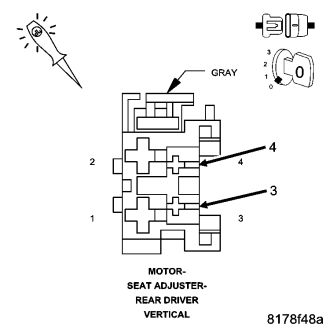
Disconnect the Rear Driver Vertical Seat Adjuster Motor.
NOTE: Check connectors – Clean and repair as necessary.
Move the Seat Switch in the rear vertical position during the next step.
Using a 12-volt test light connect one lead to the (G402) Driver Seat Rear Vertical Position Sense circuit and the other lead to Driver Seat Rear Vertical Sensor Ground at the Driver Rear Vertical Seat Adjuster Motor connector.
Does the test light illuminate for approximately two seconds then turn off with the seat switch engaged?
Yes
- Go To 4
No
- Go To 5
4. CHECK THE DRIVER SEAT REAR VERTICAL UP/DOWN DRIVER VOLTAGE
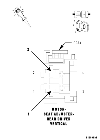
Move the Seat Switch in the rear vertical position during the next step.
Using a 12-volt test light connect one lead to the (P111) Driver Seat Rear Vertical Up Driver circuit and the other lead to (P113) Driver Seat Rear Vertical Down Driver circuit at the Rear Driver Vertical Seat Adjuster Motor connector.
Does the test light illuminate with the seat switch engaged?
Yes
- Replace the Rear Driver Vertical Seat Adjuster motor assembly.
- Perform POWER SEAT SYSTEM VERIFICATION TEST – VER 1
No
- Go To 7
5. CHECK THE (G402) DRIVER SEAT REAR VERTICAL POSITION SENSE WIRE FOR AN OPEN
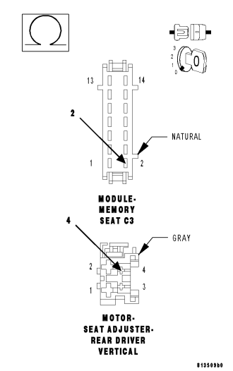
Disconnect the Memory Seat Module C3 connector.
NOTE: Check connectors – Clean and repair as necessary.
Measure the resistance of the (G402) Driver Seat Rear Vertical Position Sense circuit at the Rear Driver Vertical Seat Adjuster Motor connector to the C3 connector.
Is the resistance above 1.0 ohm?
Yes
- Repair the (G402) Driver Seat Rear Vertical Position Sense circuit for an open.
- Perform POWER SEAT SYSTEM VERIFICATION TEST – VER 1
No
- Go To 6
6. CHECK THE (G492) DRIVER SEAT REAR VERTICAL SENSOR GROUND FOR AN OPEN
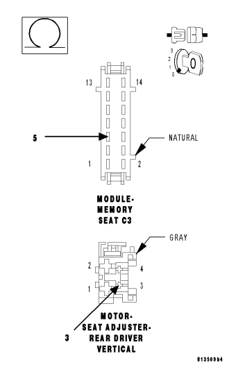
Measure the resistance of the (G492) Driver Seat Rear Vertical Sensor Ground circuit at the Driver Rear Vertical Seat Adjuster Motor connector to the C3 connector.
Is the resistance above 1.0 ohm?
Yes
- Repair the (G492) Driver Seat Rear Vertical Sensor Ground circuit for an open.
- Perform MEMORY SYSTEM VERIFICATION TEST – VER 1
No
- Replace the Memory Seat Module.
- Perform POWER SEAT SYSTEM VERIFICATION TEST – VER 1
7. CHECK THE (P111) DRIVER SEAT REAR VERTICAL UP DRIVER WIRE FOR AN OPEN
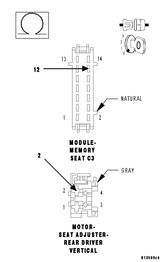
Disconnect the Memory Seat Module C3 connector.
NOTE: Check connectors – Clean and repair as necessary.
Measure the resistance of the (P111) Driver Seat Rear Vertical Up Driver circuit at the Driver Rear Vertical Seat Adjuster Motor connector to the C3 connector.
Is the resistance above 1.0 ohm?
Yes
- Repair the (P111) Driver Seat Rear Vertical Up Driver circuit for an open.
- Perform POWER SEAT SYSTEM VERIFICATION TEST – VER 1
No
- Go To 8
8. CHECK THE (P113) DRIVER SEAT REAR VERTICAL DOWN DRIVER FOR AN OPEN
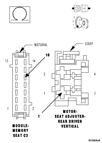
Measure the resistance of the (P113) Driver Seat Rear Vertical Down Driver circuit at the Driver Rear Vertical Seat Adjuster Motor connector to the C3 connector.
Is the resistance above 1.0 ohm?
Yes
- Repair the (P113) Driver Seat Rear Vertical Down Driver circuit for an open.
- Perform POWER SEAT SYSTEM VERIFICATION TEST – VER 1
No
- Replace the Memory Seat Module.
- Perform POWER SEAT SYSTEM VERIFICATION TEST – VER 1