DIAGNOSIS AND TESTING
- B1841-SUNROOF OPEN SWITCH INPUT CIRCUIT HIGH
- B1844-SUNROOF CLOSE SWITCH INPUT CIRCUIT HIGH
- B1847-SUNROOF VENT SWITCH INPUT CIRCUIT HIGH
- B2227-SUNROOF ECU INTERNAL
- U0141-LOST COMMUNICATION WITH FRONT CONTROL MODULE
- U0155-LOST COMMUNICATION WITH CLUSTER/CCN
- U0019-CAN B BUS
- B210D-BATTERY VOLTAGE LOW - SUNROOF
- B210E-BATTERY VOLTAGE HIGH
B1841-SUNROOF OPEN SWITCH INPUT CIRCUIT HIGH
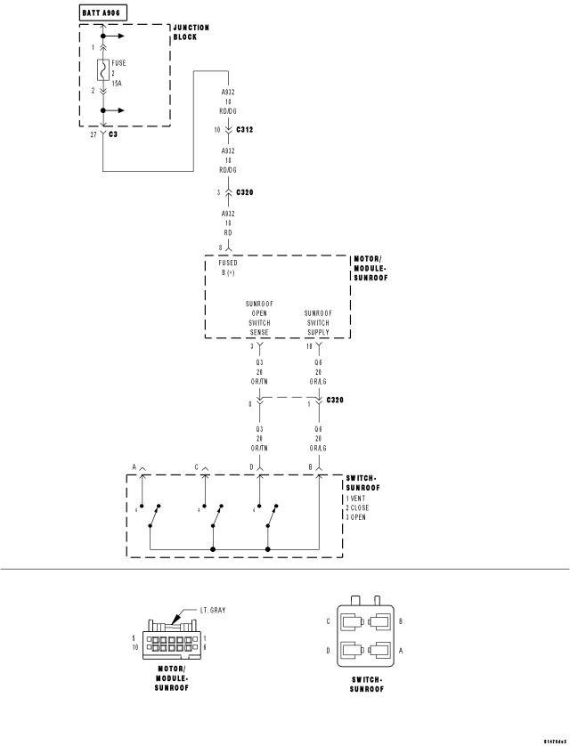
For a complete wiring diagram Refer to Section 8W.
Theory of Operation
The Sunroof Motor/Module supplies a 12 volt supply circuit to the sunroof switch. When the switch is closed to any of the 3 sense circuits (open, close or vent), it sends that command back to the module.
- When Monitored:
Whenever the Sunroof module is awake.
- Set Condition:
Whenever the module has determined that the open switch has been applied for over 15 seconds or there is a short to voltage on the Sunroof Open Switch Sense circuit, this code will set.
| Possible Causes |
| (Q3) SUNROOF OPEN SWITCH SENSE CIRCUIT SHORT TO VOLTAGE |
| (Q3) SUNROOF OPEN SWITCH SENSE CIRCUIT SHORT TO (Q6) SUNROOF SWITCH SUPPLY CIRCUIT |
| SUNROOF SWITCH SHORTED |
| SUNROOF MOTOR/MODULE |
Diagnostic Test
1. TEST FOR INTERMITTENT CONDITIONTurn the ignition on.
With the scan tool, record and erase DTC's
Press and release the Sunroof Switch in all positions several times.
Wait 30 seconds.
With the scan tool, read DTC's.
Does the scan tool display B1841–SUNROOF OPEN SWITCH INPUT CIRCUIT HIGH?
Yes
- Go To 2
No
- The conditions that caused this code to set are not present at this time. Check the switch for any binding conditions and using the wiring diagram/schematic as a guide, inspect the wiring and connectors.
2. SUNROOF SWITCH SHORTED
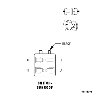
With the scan tool, erase DTC's.
Turn the ignition off.
Disconnect the Sunroof Switch connector.
Turn the ignition on and wait 30 seconds.
With the scan tool, read DTC's.
Does the scan tool display B1841–SUNROOF OPEN SWITCH INPUT CIRCUIT HIGH?
Yes
- Go To 3
No
- Replace the Sunroof Switch.
- Perform BODY VERIFICATION TEST - VER 1. (Refer to 8 - ELECTRICAL/ELECTRONIC CONTROL MODULES - STANDARD PROCEDURE)
3. (Q3) SUNROOF OPEN SWITCH SENSE CIRCUIT SHORT TO VOLTAGE
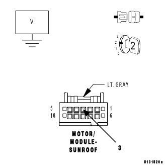
NOTE: To further diagnose the sunroof, it is necessary to lower or remove the headliner.
Turn the ignition off.
Lower the headliner to gain access to the Sunroof Motor/Module connector.
Disconnect the Sunroof Motor/Module connector.
NOTE: Ensure the A-Pillar connector is connected before proceeding.
Turn the ignition on.
Measure the voltage between the (Q3) Sunroof Open Switch Sense circuit and Ground.
Is the voltage above 0.4 volts?
Yes
- Repair the (Q3) Sunroof Open Switch Sense circuit for a short to voltage.
- Perform BODY VERIFICATION TEST - VER 1. (Refer to 8 - ELECTRICAL/ELECTRONIC CONTROL MODULES - STANDARD PROCEDURE)
No
- Go To 4
4. (Q3) SUNROOF OPEN SWITCH SENSE CIRCUIT SHORT TO (Q6) SUNROOF SWITCH SUPPLY CIRCUIT
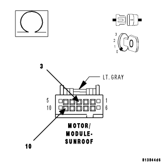
Turn the ignition off.
Disconnect the A-Pillar connector.
Measure the resistance between the (Q3) Sunroof Open Switch Sense circuit and the (Q6) Sunroof Switch Supply circuit in the Sunroof Motor/Module connector.
Is the resistance below 1000.0 ohms?
Yes
- Repair the (Q3) Sunroof Open Switch Sense circuit for a short to the (Q6) Sunroof Switch Supply circuit.
- Perform BODY VERIFICATION TEST - VER 1. (Refer to 8 - ELECTRICAL/ELECTRONIC CONTROL MODULES - STANDARD PROCEDURE)
No
- Replace the Sunroof Motor/Module.
- Perform the Sunroof Position Calibration, (Refer to 8 - ELECTRICAL/POWER TOP/MOTOR - STANDARD PROCEDURE - SUNROOF POSITION CALIBRATION). Perform the Excessive Force Limitation Calibration, (Refer to 8 - ELECTRICAL/POWER TOP/MOTOR - STANDARD PROCEDURE - EXCESSIVE FORCE LIMITATION CALIBRATION).
- Perform BODY VERIFICATION TEST - VER 1. (Refer to 8 - ELECTRICAL/ELECTRONIC CONTROL MODULES - STANDARD PROCEDURE)
B1844-SUNROOF CLOSE SWITCH INPUT CIRCUIT HIGH
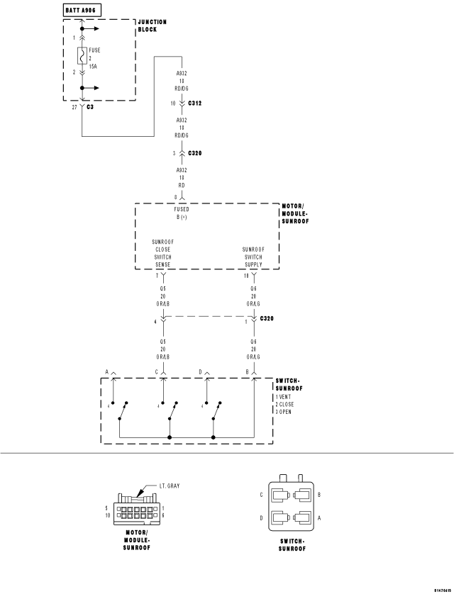
For a complete wiring diagram Refer to Section 8W.
Theory of Operation
The Sunroof Motor/Module supplies a 12 volt supply circuit to the sunroof switch. When the switch is closed to any of the 3 sense circuits (open, close or vent), it sends that command back to the module.
- When Monitored:
Whenever the Sunroof module is awake.
- Set Condition:
Whenever the module has determined that the close switch has been applied for over 15 seconds or there is a short to voltage on the Sunroof Close Switch Sense circuit, this code will set.
| Possible Causes |
| (Q5) SUNROOF CLOSE SWITCH SENSE CIRCUIT SHORT TO VOLTAGE |
| (Q5) SUNROOF CLOSE SWITCH SENSE CIRCUIT SHORT TO (Q6) SUNROOF SWITCH SUPPLY CIRCUIT |
| SUNROOF SWITCH SHORTED |
| SUNROOF MOTOR/MODULE |
Diagnostic Test
1. TEST FOR INTERMITTENT CONDITIONTurn the ignition on.
With the scan tool, record and erase DTC's
Press and release the Sunroof Switch in all positions several times.
Wait 30 seconds.
With the scan tool, read DTC's.
Does the scan tool display B1844–SUNROOF CLOSE SWITCH INPUT CIRCUIT HIGH?
Yes
- Go To 2
No
- The conditions that caused this code to set are not present at this time. Check the switch for any binding conditions and using the wiring diagram/schematic as a guide, inspect the wiring and connectors.
2. SUNROOF SWITCH SHORTED
With the scan tool, erase DTC's.
Turn the ignition off.
Disconnect the Sunroof Switch connector.
Turn the ignition on and wait 30 seconds.
With the scan tool, read DTC's.
Does the scan tool display B1844–SUNROOF CLOSE SWITCH INPUT CIRCUIT HIGH?
Yes
- Go To 3
No
- Replace the Sunroof Switch.
- Perform BODY VERIFICATION TEST - VER 1. (Refer to 8 - ELECTRICAL/ELECTRONIC CONTROL MODULES - STANDARD PROCEDURE)
3. (Q5) SUNROOF CLOSE SWITCH SENSE CIRCUIT SHORT TO VOLTAGE
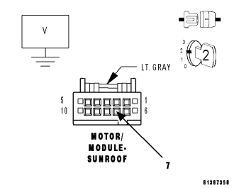
NOTE: To further diagnose the sunroof, it is necessary to lower or remove the headliner.
Turn the ignition off.
Lower the headliner to gain access to the Sunroof Motor/Module connector.
Disconnect the Sunroof Motor/Module connector.
NOTE: Ensure the A-Pillar connector is connected before proceeding.
Turn the ignition on.
Measure the voltage between the (Q5) Sunroof Close Switch Sense circuit and Ground.
Is the voltage above 0.4 volts?
Yes
- Repair the (Q5) Sunroof Close Switch Sense circuit for a short to voltage.
- Perform BODY VERIFICATION TEST - VER 1. (Refer to 8 - ELECTRICAL/ELECTRONIC CONTROL MODULES - STANDARD PROCEDURE)
No
- Go To 4
4. (Q5) SUNROOF CLOSE SWITCH SENSE CIRCUIT SHORT TO (Q6) SUNROOF SWITCH SUPPLY CIRCUIT
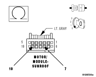
Turn the ignition off.
Disconnect the A-Pillar connector.
Measure the resistance between the (Q5) Sunroof Close Switch Sense circuit and the (Q6) Sunroof Switch Supply circuit in the Sunroof Motor/Module connector.
Is the resistance below 1000.0 ohms?
Yes
- Repair the (Q5) Sunroof Close Switch Sense circuit for a short to the (Q6) Sunroof Switch Supply circuit.
- Perform BODY VERIFICATION TEST - VER 1. (Refer to 8 - ELECTRICAL/ELECTRONIC CONTROL MODULES - STANDARD PROCEDURE)
No
- Replace the Sunroof Motor/Module.
- Perform the Sunroof Position Calibration, (Refer to 8 - ELECTRICAL/POWER TOP/MOTOR - STANDARD PROCEDURE - SUNROOF POSITION CALIBRATION). Perform the Excessive Force Limitation Calibration, (Refer to 8 - ELECTRICAL/POWER TOP/MOTOR - STANDARD PROCEDURE - EXCESSIVE FORCE LIMITATION CALIBRATION).
- Perform BODY VERIFICATION TEST - VER 1. (Refer to 8 - ELECTRICAL/ELECTRONIC CONTROL MODULES - STANDARD PROCEDURE)
B1847-SUNROOF VENT SWITCH INPUT CIRCUIT HIGH
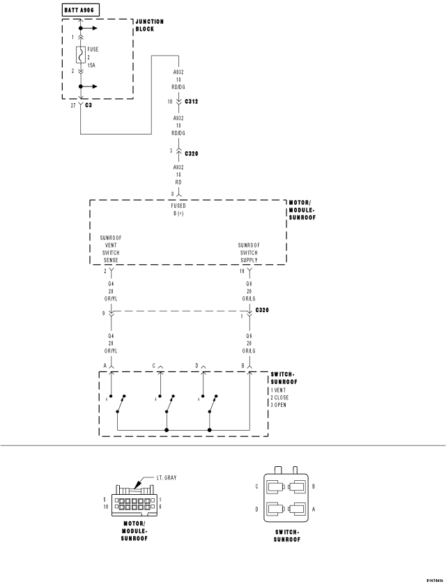
For a complete wiring diagram Refer to Section 8W.
Theory of Operation
The Sunroof Motor/Module supplies a 12 volt supply circuit to the sunroof switch. When the switch is closed to any of the 3 sense circuits (open, close or vent), it sends that command back to the module.
- When Monitored:
Whenever the Sunroof module is awake.
- Set Condition:
Whenever the module has determined that the vent switch has been applied for over 15 seconds or there is a short to voltage on the Sunroof Vent Switch Sense circuit, this code will set.
| Possible Causes |
| (Q4) SUNROOF VENT SWITCH SENSE CIRCUIT SHORT TO VOLTAGE |
| (Q4) SUNROOF VENT SWITCH SENSE CIRCUIT SHORT TO (Q6) SUNROOF SWITCH SUPPLY CIRCUIT |
| SUNROOF SWITCH SHORTED |
| SUNROOF MOTOR/MODULE |
Diagnostic Test
1. TEST FOR INTERMITTENT CONDITIONTurn the ignition on.
With the scan tool, record and erase DTC's
Press and release the Sunroof Switch in all positions several times.
Wait 30 seconds.
With the scan tool, read DTC's.
Does the scan tool display B1847–SUNROOF VENT SWITCH INPUT CIRCUIT HIGH?
Yes
- Go To 2
No
- The conditions that caused this code to set are not present at this time. Check the switch for any binding conditions and using the wiring diagram/schematic as a guide, inspect the wiring and connectors.
2. SUNROOF SWITCH SHORTED
With the scan tool, erase DTC's.
Turn the ignition off.
Disconnect the Sunroof Switch connector.
Turn the ignition on and wait 30 seconds.
With the scan tool, read DTC's.
Does the scan tool display B1847–SUNROOF VENT SWITCH INPUT CIRCUIT HIGH?
Yes
- Go To 3
No
- Replace the Sunroof Switch.
- Perform BODY VERIFICATION TEST - VER 1. (Refer to 8 - ELECTRICAL/ELECTRONIC CONTROL MODULES - STANDARD PROCEDURE)
3. (Q4) SUNROOF VENT SWITCH SENSE CIRCUIT SHORT TO VOLTAGE
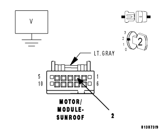
NOTE: To further diagnose the sunroof, it is necessary to lower or remove the headliner.
Turn the ignition off.
Lower the headliner to gain access to the Sunroof Motor/Module connector.
Disconnect the Sunroof Motor/Module connector.
NOTE: Ensure the A-Pillar connector is connected before proceeding.
Turn the ignition on.
Measure the voltage between the (Q4) Sunroof Vent Switch Sense circuit and Ground.
Is the voltage above 0.4 volts?
Yes
- Repair the (Q4) Sunroof Vent Switch Sense circuit for a short to voltage.
- Perform BODY VERIFICATION TEST - VER 1. (Refer to 8 - ELECTRICAL/ELECTRONIC CONTROL MODULES - STANDARD PROCEDURE)
No
- Go To 4
4. (Q4) SUNROOF VENT SWITCH SENSE CIRCUIT SHORT TO (Q6) SUNROOF SWITCH SUPPLY CIRCUIT
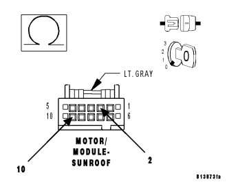
Turn the ignition off.
Disconnect the A-Pillar connector.
Measure the resistance between the (Q4) Sunroof Vent Switch Sense circuit and the (Q6) Sunroof Switch Supply circuit in the Sunroof Motor/Module connector.
Is the resistance below 1000.0 ohms?
Yes
- Repair the (Q4) Sunroof Vent Switch Sense circuit for a short to the (Q6) Sunroof Switch Supply circuit.
- Perform BODY VERIFICATION TEST - VER 1. (Refer to 8 - ELECTRICAL/ELECTRONIC CONTROL MODULES - STANDARD PROCEDURE)
No
- Replace the Sunroof Motor/Module.
- Perform the Sunroof Position Calibration, (Refer to 8 - ELECTRICAL/POWER TOP/MOTOR - STANDARD PROCEDURE - SUNROOF POSITION CALIBRATION). Perform the Excessive Force Limitation Calibration, (Refer to 8 - ELECTRICAL/POWER TOP/MOTOR - STANDARD PROCEDURE - EXCESSIVE FORCE LIMITATION CALIBRATION).
- Perform BODY VERIFICATION TEST - VER 1. (Refer to 8 - ELECTRICAL/ELECTRONIC CONTROL MODULES - STANDARD PROCEDURE)
B2227-SUNROOF ECU INTERNAL
For a complete wiring diagram Refer to Section 8W.
- When Monitored:
Whenever the Sunroof module is awake.
- Set Condition:
Whenever the module has determined that there is a motor or electronic malfunction, this code will set.
| Possible Causes |
| SUNROOF MOTOR/MODULE |
Diagnostic Test
1. TEST FOR INTERMITTENT CONDITIONTurn the ignition on.
With the scan tool, record and erase DTC's
Operate the Sunroof Switch in all positions several times.
Wait 30 seconds.
With the scan tool, read DTC's.
Does the scan tool display B2227–SUNROOF ECU INTERNAL?
Yes
- Replace the Sunroof Motor/Module.
- Perform the Sunroof Position Calibration, (Refer to 8 - ELECTRICAL/POWER TOP/MOTOR - STANDARD PROCEDURE - SUNROOF POSITION CALIBRATION). Perform the Excessive Force Limitation Calibration, (Refer to 8 - ELECTRICAL/POWER TOP/MOTOR - STANDARD PROCEDURE - EXCESSIVE FORCE LIMITATION CALIBRATION).
- Perform BODY VERIFICATION TEST - VER 1. (Refer to 8 - ELECTRICAL/ELECTRONIC CONTROL MODULES - STANDARD PROCEDURE)
No
- The conditions that caused this code to set are not present at this time. Operate the Sunroof several times and recheck for DTC's. If the code reappears now or later, replace the Sunroof Motor/Module.
U0141-LOST COMMUNICATION WITH FRONT CONTROL MODULE
For a complete wiring diagram Refer to Section 8W.
(Refer to 8 - ELECTRICAL/ELECTRONIC CONTROL MODULES - DIAGNOSIS AND TESTING) for the diagnostic test procedure.
U0155-LOST COMMUNICATION WITH CLUSTER/CCN
For a complete wiring diagram Refer to Section 8W.
(Refer to 8 - ELECTRICAL/ELECTRONIC CONTROL MODULES - DIAGNOSIS AND TESTING) for the diagnostic test procedure.
U0019-CAN B BUS
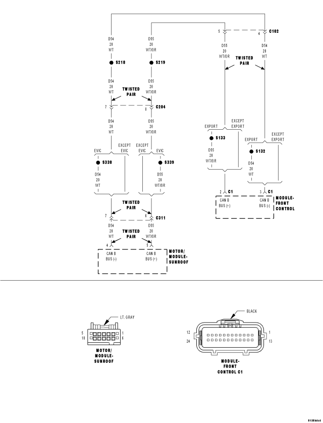
For a complete wiring diagram Refer to Section 8W.
- When Monitored:
Continuously
- Set Condition:
Whenever the CAN B Bus (+) or CAN B Bus (-) circuit is open, shorted to voltage or shorted to ground.
| Possible Causes |
| CAN B BUS DTC's IN FRONT CONTROL MODULE |
| (D55) CAN B BUS (+) CIRCUIT OPEN |
| (D54) CAN B BUS (-) CIRCUIT OPEN |
| SUNROOF MOTOR/MODULE |
Diagnostic Test
1. CHECK FOR ACTIVE DTCSWith the scan tool, read the active DTC's.
Cycle the ignition switch from off to on at least 5 times, leaving the ignition on for a minimum of 90 seconds per cycle.
Turn the ignition off and wait 30 seconds.
Turn the ignition on.
With the scan tool, read the active DTC's.
Does the scan tool display this DTC as active?
Yes
- Go To 2
No
- If the DTC is stored, check for an intermittent condition. Visually inspect the related wiring harness connectors. Look for broken, bent, pushed out, or corroded terminals.
2. CHECK FRONT CONTROL MODULE DTC's
With the scan tool, read Front Control Module active DTC's
Does the scan tool display any CAN B BUS DTC's – ACTIVE?
Yes
No
- Go To 3
3. (D55) CAN B BUS (+) CIRCUIT OPEN
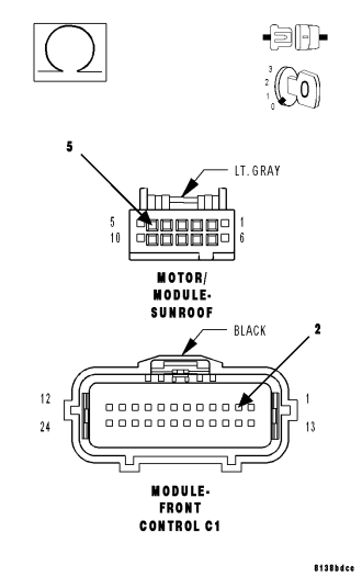
Turn the ignition off.
Disconnect the negative battery cable.
Disconnect the Sunroof Motor/Module connector.
Disconnect the Front Control Module C1 connector.
Measure the resistance of the (D55) CAN B Bus (+) circuit between the Front Control Module C1 connector and the Sunroof Motor/Module connector.
Is the resistance below 2.0 ohms?
Yes
- Go To 4
No
- Repair the (D55) CAN B Bus (+) circuit for an open.
- Perform BODY VERIFICATION TEST – VER 1. (Refer to 8 - ELECTRICAL/ELECTRONIC CONTROL MODULES - STANDARD PROCEDURE)
4. (D54) CAN B BUS (–) CIRCUIT OPEN
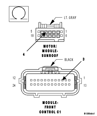
Measure the resistance of the (D54) CAN B Bus (–) circuit between the Front Control Module C1 connector and the Sunroof Motor/Module connector.
Is the resistance below 2.0 ohms?
Yes
- Replace the Sunroof Motor/Module in accordance with the service information.
- Perform the Sunroof Position Calibration, (Refer to 8 - ELECTRICAL/POWER TOP/MOTOR - STANDARD PROCEDURE - SUNROOF POSITION CALIBRATION). Perform the Excessive Force Limitation Calibration, (Refer to 8 - ELECTRICAL/POWER TOP/MOTOR - STANDARD PROCEDURE - EXCESSIVE FORCE LIMITATION CALIBRATION).
- Perform BODY VERIFICATION TEST - VER 1. (Refer to 8 - ELECTRICAL/ELECTRONIC CONTROL MODULES - STANDARD PROCEDURE)
No
- Repair the (D54) CAN B Bus (–) circuit for an open.
- Perform BODY VERIFICATION TEST – VER 1. (Refer to 8 - ELECTRICAL/ELECTRONIC CONTROL MODULES - STANDARD PROCEDURE)
B210D-BATTERY VOLTAGE LOW - SUNROOF
For a complete wiring diagram Refer to Section 8W.
- When Monitored:
At all times.
- Set Condition:
Anytime the module senses voltage input below 9.0 volts (motor operating or not). After this code is set, it becomes stored when the voltage exceeds 9.1 volts.
| POSSIBLE CAUSES |
| LOW VOLTAGE ENGINE DTC |
| (A932) FUSED B(+) CIRCUIT RESISTED |
| SUNROOF MOTOR/MODULE |
Diagnostic Test
1. CHECK ENGINE DTC'sNOTE: Ensure the battery is fully charged before proceeding.
With the scan tool, read ENGINE DTC's
Are there any ENGINE BATTERY OR CHARGING SYSTEM DTC's present?
No
- Go to 2
Yes
- Refer to symptom list for problems related to ENGINE.
2. TEST FOR INTERMITTENT CONDITION
With the scan tool, record and erase DTC's
Start the engine and run for 2 minutes.
Cycle the ignition from on to off 3 times.
Turn the ignition on.
With the scan tool, read DTC's.
Does the scan tool display BATTERY VOLTAGE LOW in the Sunroof module only?
Yes
- Go To 3
No
- The conditions that caused this code to set are not present at this time. Using the wiring diagram/schematic as a guide, inspect the wiring and connectors.
- Perform BODY VERIFICATION TEST - VER 1. (Refer to 8 - ELECTRICAL/ELECTRONIC CONTROL MODULES - STANDARD PROCEDURE)
3. (A932) FUSED B(+) CIRCUIT RESISTED
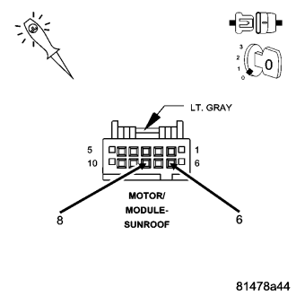
Turn the ignition off.
Lower the headliner and disconnect the Sunroof Motor/Module connector.
Test for a resisted (A932) Fused B(+) circuit by connecting a 12-volt test light between the (A932) Fused B(+) circuit and the (Z914) Ground circuit in the Sunroof Motor/Module connector. The test light must illuminate brightly. Compare the brightness to that of a direct connection to the battery.
Does the test light illuminate brightly?
Yes
- Replace the Sunroof Motor/Module in accordance with Service Information. (Refer to 8 - ELECTRICAL/POWER TOP/MOTOR - REMOVAL)
- Perform BODY VERIFICATION TEST - VER 1. (Refer to 8 - ELECTRICAL/ELECTRONIC CONTROL MODULES - STANDARD PROCEDURE)
No
- Test the (A932) Fused B(+) and the (Z914) Ground circuits to determine which circuit is resisted. Repair the (A932) Fused B(+) circuit or the (Z914) Ground circuit for high resistance.
- Perform BODY VERIFICATION TEST - VER 1. (Refer to 8 - ELECTRICAL/ELECTRONIC CONTROL MODULES - STANDARD PROCEDURE)
B210E-BATTERY VOLTAGE HIGH
For a complete wiring diagram Refer to Section 8W.
- When Monitored:
At all times.
- Set Condition:
Anytime the module senses voltage input above 16 volts. This code will become stored when the voltage drops below 15.9 volts.
| POSSIBLE CAUSES |
| HIGH VOLTAGE ENGINE DTC |
| SUNROOF MOTOR/ MODULE |
Diagnostic Test
1. CHECK ENGINE DTC'sWith the scan tool, read ENGINE DTC's
Are there any ENGINE DTC's present?
No
- Go to 2
Yes
- Refer to symptom list for problems related to ENGINE.
2. TEST FOR INTERMITTENT CONDITION
With the scan tool, record and erase DTC's
Start the engine and run for two minutes.
Cycle the ignition from on to off three times.
Turn the ignition on.
With the scan tool, read DTC's.
Does the scan tool display BATTERY VOLTAGE HIGH in this module only?
Yes
- Replace the Sunroof Motor/Module in accordance with service information. (Refer to 8 - ELECTRICAL/POWER TOP/MOTOR - REMOVAL)
- Perform BODY VERIFICATION TEST - VER 1. (Refer to 8 - ELECTRICAL/ELECTRONIC CONTROL MODULES - STANDARD PROCEDURE)
No
- The conditions that caused this code to set are not present at this time. Using the wiring diagram/schematic as a guide, inspect the wiring and connectors.
- Perform BODY VERIFICATION TEST - VER 1. (Refer to 8 - ELECTRICAL/ELECTRONIC CONTROL MODULES - STANDARD PROCEDURE)