STANDARD PROCEDURE
CONNECTING ROD BEARING FITTING
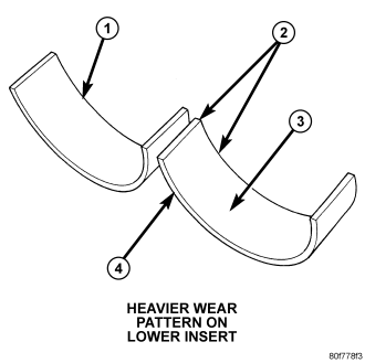
Inspect the connecting rod bearings for scoring (1) and (3). Check the bearings for normal wear patterns, scoring, grooving, fatigue and pitting. Replace any bearing that shows abnormal wear.
Inspect the connecting rod journals for signs of scoring, nicks and burrs.
Misaligned or bent connecting rods can cause abnormal wear on pistons, piston rings, cylinder walls, connecting rod bearings and crankshaft connecting rod journals. If wear patterns or damage to any of these components indicate the probability of a misaligned connecting rod, inspect it for correct rod alignment. Replace misaligned, bent or twisted connecting rods.
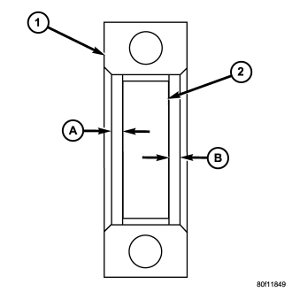
1. Wipe the oil from the connecting rod journal.
2. Lubricate the upper bearing insert (2) and position in connecting rod (1). Center bearing insert in connecting rod
3. Measure at point A and point B. Measurement should be less then .50mm (.0196 in.).
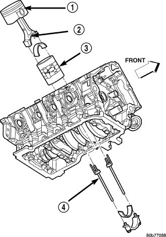
4. Use piston ring compressor (3) and Guide Pins Special Tool 8507 (4) to install the rod and piston assemblies. The oil slinger slots in the rods must face front of the engine. The “F”'s (1) near the piston wrist pin bore should point to the front of the engine.
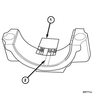
5. Install the lower bearing insert in the bearing cap. Center bearing insert in connecting rod . The lower insert must be dry. Place strip of Plastigage (1) across full width of the lower insert at the center of bearing cap. Plastigage must not crumble in use. If brittle, obtain fresh stock.
6. Install bearing cap and connecting rod on the journal and tighten bolts to 27 N·m (20 ft. lbs.) plus a 90° turn. DO NOT rotate crankshaft. Plastigage will smear, resulting in inaccurate indication.
7. Remove the bearing cap and determine amount of bearing-to-journal clearance by measuring the width of compressed Plastigage (2). Refer to Engine Specifications for the proper clearance. Plastigage should indicate the same clearance across the entire width of the insert. If the clearance varies, it may be caused by either a tapered journal, bent connecting rod or foreign material trapped between the insert and cap or rod.
8. If the correct clearance is indicated, replacement of the bearing inserts is not necessary. Remove the Plastigage from crankshaft journal and bearing insert. Proceed with installation.
9. If bearing-to-journal clearance exceeds the specification, determin which services bearing set to use the bearing sizes are as follows:
| Bearing Mark | SIZE | USED WITH JOURNAL SIZE |
| .025 US | .025 mm | 57.883-57.867 mm |
| (.001 in.) | (2.2788-2.2783 in.) | |
| Std. | STANDARD | 57.908-57.892 mm |
| (2.2798-2.2792 in.) | ||
| .250 US | .250 mm | 57.658-57.646 mm |
| (.010 in.) | (2.2700-2.2695 in.) |
CAUTION: Connecting Rod Bolts are Torque to Yield Bolts and Must Not Be Reused. Always replace the Rod Bolts whenever they are loosened or removed.
10. Repeat the Plastigage measurement to verify your bearing selection prior to final assembly.
11. Once you have selected the proper insert, install the insert and cap. Tighten the connecting rod bolts to 27 N·m (20 ft. lbs.) plus a 90° turn.
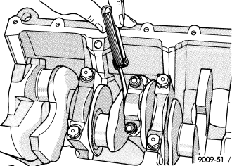
Slide snug-fitting feeler gauge between the connecting rod and crankshaft journal flange . Refer to Engine Specifications for the proper clearance. Replace the connecting rod if the side clearance is not within specification.
PISTON FITTING
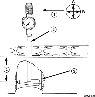
1. To correctly select the proper size piston, a cylinder bore gauge (2), capable of reading in 0.003 mm ( .0001 in.) INCREMENTS is required. If a bore gauge is not available, do not use an inside micrometer.
2. Measure the inside diameter of the cylinder bore at a point 38.0 mm (1.5 inches) below top of bore (4). Start perpendicular (across or at 90 degrees) to the axis of the crankshaft at point A and then take an additional bore reading 90 degrees to that at point B.
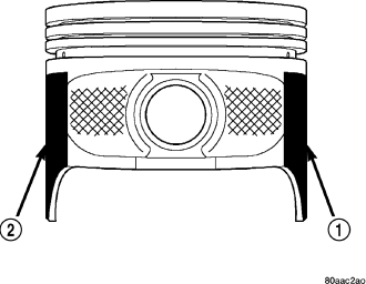
3. The coated pistons will be serviced with the piston pin and connecting rod pre-assembled.
4. The coating material (1) and (2) is applied to the piston after the final piston machining process. Measuring the outside diameter of a coated piston will not provide accurate results. Therefore measuring the inside diameter of the cylinder bore with a dial Bore Gauge is MANDATORY. To correctly select the proper size piston, a cylinder bore gauge capable of reading in 0.003 mm (.0001 in.) increments is required.
5. Piston installation into the cylinder bore requires slightly more pressure than that required for non-coated pistons. The bonded coating on the piston will give the appearance of a line-to-line fit with the cylinder bore.