C140F-TRANSFER CASE RANGE POSITION SENSOR ERRATIC PERFORMANCE
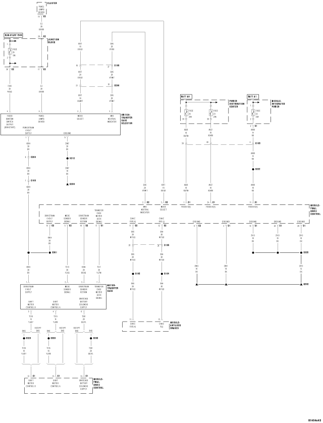
For a complete wiring diagram Refer to Section 8W
- When Monitored:
With the ignition on and no system undervoltage or overvoltage condition present.
- Set Condition:
The Final Drive Control Module detects excessive voltage fluctuation on the Mode Sensor Signal circuit.
| Possible Causes |
| (K504) DRIVETRAIN 5 VOLT SUPPLY CIRCUIT SHORT TO VOLTAGE |
| (K504) DRIVETRAIN 5 VOLT SUPPLY CIRCUIT HIGH RESISTANCE |
| (K504) DRIVETRAIN 5 VOLT SUPPLY CIRCUIT SHORT TO GROUND |
| (T313) MODE SENSOR SIGNAL CIRCUIT SHORT TO VOLTAGE |
| (T313) MODE SENSOR SIGNAL CIRCUIT HIGH RESISTANCE |
| (T313) MODE SENSOR SIGNAL CIRCUIT SHORT TO GROUND |
| (K594) DRIVETRAIN SENSOR RETURN CIRCUIT SHORT TO VOLTAGE |
| (K594) DRIVETRAIN SENSOR RETURN CIRCUIT HIGH RESISTANCE |
| TRANSFER CASE MOTOR |
| FINAL DRIVE CONTROL MODULE |
Diagnostic Test
1. DTC IS ACTIVENOTE: This DTC sets when the Final Drive Control Module detects excessive voltage fluctuation on the Mode Sensor Signal circuit. Perform a thorough inspection of all wiring and connectors between the sensor and the control module.
Ignition on, engine not running.
With the scan tool, read DTCs in the Final Drive Control Module.
Is the status Active for this DTC?
Yes
- Go to 2
No
- Go to 13
2. (T504) DRIVETRAIN 5 VOLT SUPPLY VOLTAGE ERRATIC
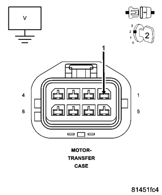
NOTE: This DTC sets when the Final Drive Control Module detects excessive voltage fluctuation on the Mode Sensor Signal circuit. Perform a thorough inspection of all wiring and connectors between the sensor and the control module.
Turn the ignition off to the lock position
Disconnect the Transfer Case Motor harness connector.
Ignition on, engine not running.
Measure the voltage of the (T504) Drivetrain 5-volt Supply circuit.
NOTE: Voltage should be approximately 5.0 volts and steady. Compare any slight fluctuations found to a known good circuit in order to verify voltmeter functionality.
Is the voltage approximately 5.0 volts and steady?
Yes
- Go to 6
No
- Go to 3
3. (T504) DRIVETRAIN 5 VOLT SUPPLY CIRCUIT INTERMITTENT SHORT TO VOLTAGE
Turn the ignition off to the lock position
Disconnect the Final Drive Control Module C2 harness connector.
Ignition on, engine not running.
Measure the voltage of the (T504) Drivetrain 5-volt Supply circuit.
Monitor the voltmeter while performing a wiggle test on the wiring harness and connectors.
Is any voltage detected on the circuit during the wiggle test?
Yes
- Repair the (T504) Drivetrain 5-volt Supply circuit for an intermittent short to voltage.
- Perform the TRANSFER CASE VERIFICATION TEST-VER 1 (Refer to 21 - TRANSMISSION/TRANSAXLE/TRANSFER CASE - STANDARD PROCEDURE).
No
- Go to 4
4. (T504) DRIVETRAIN 5 VOLT SUPPLY CIRCUIT HIGH RESISTANCE
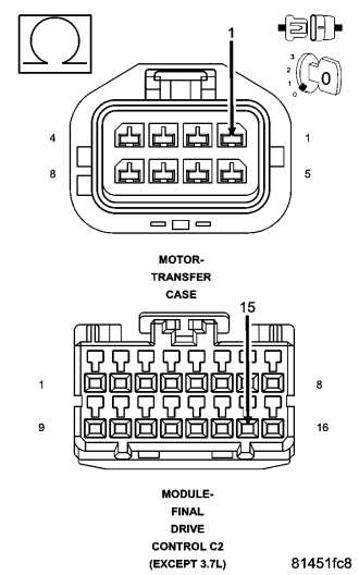
Measure the resistance of the (T504) Drivetrain 5-volt Supply circuit between the Transfer Case Motor harness connector and the Final Drive Control Module C2 harness connector.
Monitor the ohmmeter while performing a wiggle test on the wiring harness and connectors.
Is the resistance ever above 5.0 ohms during the wiggle test?
Yes
- Repair the (T504) Drivetrain 5-volt Supply circuit for an intermittent open circuit or high resistance.
- Perform the TRANSFER CASE VERIFICATION TEST-VER 1 (Refer to 21 - TRANSMISSION/TRANSAXLE/TRANSFER CASE - STANDARD PROCEDURE).
No
- Go to 5
5. (T504) DRIVETRAIN 5 VOLT SUPPLY CIRCUIT INTERMITTENT SHORT TO GROUND
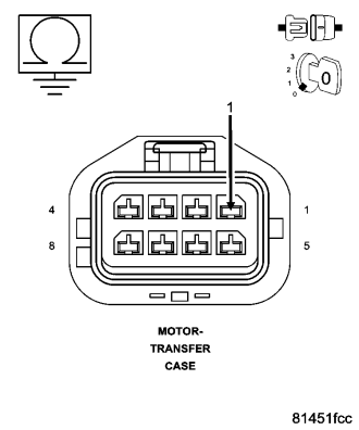
Measure the resistance between ground and the (T504) Drivetrain 5-volt Supply circuit.
Monitor the ohmmeter while performing a wiggle test on the wiring harness and connectors.
Is the resistance ever below 5.0 ohms during the wiggle test?
Yes
- Repair the (T504) Drivetrain 5-volt Supply circuit for an intermittent short to ground.
- Perform the TRANSFER CASE VERIFICATION TEST-VER 1 (Refer to 21 - TRANSMISSION/TRANSAXLE/TRANSFER CASE - STANDARD PROCEDURE).
No
- Replace the Final Drive Control Module in accordance with the Service Information.
- Perform the TRANSFER CASE VERIFICATION TEST-VER 1 (Refer to 21 - TRANSMISSION/TRANSAXLE/TRANSFER CASE - STANDARD PROCEDURE).
6. T-CASE POSITION SENSOR VOLTAGE
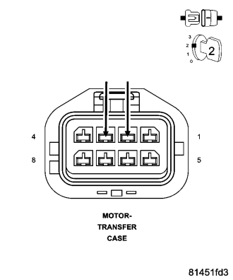
Turn the ignition off to the lock position
Reconnect the Final Drive Control Module C2 harness connector.
Connect a jumper wire between the (T313) Mode Sensor Signal circuit and the (K594) Drivetrain Sensor Return circuit in the Transfer Case Motor harness connector.
Ignition on, engine not running.
With the scan tool read the T-Case Position Sensor Voltage in the Final Drive Control Module while performing a wiggle test on the wiring and connectors between the sensor and the control module.
NOTE: Voltage should be approximately 0.0 volts and steady.
Is the T-Case Position Sensor Voltage approximately 0.0 volts and steady?
Yes
- Go to 12
No
- Go to 7
7. (T313) MODE SENSOR SIGNAL CIRCUIT INTERMITTENT SHORT TO VOLTAGE
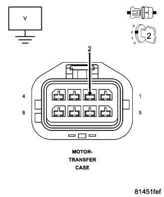
NOTE: Remove the previously installed jumper wire.
Turn the ignition off to the lock position
Disconnect the Final Drive Control Module C2 harness connector.
Ignition on, engine not running.
Measure the voltage of the (T313) Mode Sensor Signal circuit.
Monitor the voltmeter while performing a wiggle test on the wiring harness and connectors.
Is any voltage detected on the circuit during the wiggle test?
Yes
- Repair the (T313) Mode Sensor Signal circuit for an intermittent short to voltage.
- Perform the TRANSFER CASE VERIFICATION TEST-VER 1 (Refer to 21 - TRANSMISSION/TRANSAXLE/TRANSFER CASE - STANDARD PROCEDURE).
No
- Go to 8
8. (K594) DRIVETRAIN SENSOR RETURN CIRCUIT INTERMITTENT SHORT TO VOLTAGE
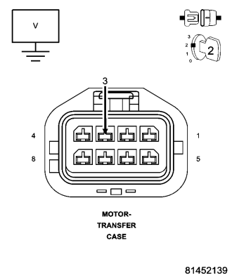
Measure the voltage of the (K594) Drivetrain Sensor Return circuit.
Monitor the voltmeter while performing a wiggle test on the wiring harness and connectors.
Is any voltage detected on the circuit during the wiggle test?
Yes
- Repair the (K594) Drivetrain Sensor Return circuit for an intermittent short to voltage.
- Perform the TRANSFER CASE VERIFICATION TEST-VER 1 (Refer to 21 - TRANSMISSION/TRANSAXLE/TRANSFER CASE - STANDARD PROCEDURE).
No
- Go to 9
9. (T313) MODE SENSOR SIGNAL CIRCUIT HIGH RESISTANCE
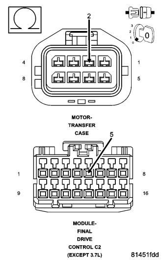
Turn the ignition off to the lock position
Measure the resistance of the (T313) Mode Sensor Signal circuit between the Transfer Case Motor harness connector and the Final Drive Control Module C2 harness connector.
Monitor the ohmmeter while performing a wiggle test on the wiring harness and connectors.
Is the resistance ever above 5.0 ohms during the wiggle test?
Yes
- Repair the (T313) Mode Sensor Signal circuit for an intermittent open circuit or high resistance.
- Perform the TRANSFER CASE VERIFICATION TEST-VER 1 (Refer to 21 - TRANSMISSION/TRANSAXLE/TRANSFER CASE - STANDARD PROCEDURE).
No
- Go to 10
10. (K594) DRIVETRAIN SENSOR RETURN CIRCUIT HIGH RESISTANCE
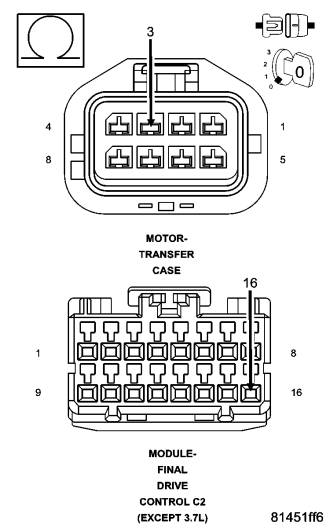
Measure the resistance of the (K594) Drivetrain Sensor Return circuit between the Transfer Case Motor harness connector and the Final Drive Control Module C2 harness connector.
Monitor the ohmmeter while performing a wiggle test on the wiring harness and connectors.
Is the resistance ever above 5.0 ohms during the wiggle test?
Yes
- Repair the (K594) Drivetrain Sensor Return circuit for an intermittent open circuit or high resistance.
- Perform the TRANSFER CASE VERIFICATION TEST-VER 1 (Refer to 21 - TRANSMISSION/TRANSAXLE/TRANSFER CASE - STANDARD PROCEDURE).
No
- Go to 11
11. (T313) MODE SENSOR SIGNAL CIRCUIT INTERMITTENT SHORT TO GROUND
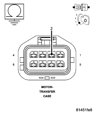
Measure the resistance between ground and the (T313) Mode Sensor Signal circuit.
Monitor the ohmmeter while performing a wiggle test on the wiring harness and connectors.
Is the resistance ever below 5.0 ohms during the wiggle test?
Yes
- Repair the (T313) Mode Sensor Signal circuit for an intermittent short to ground.
- Perform the TRANSFER CASE VERIFICATION TEST-VER 1 (Refer to 21 - TRANSMISSION/TRANSAXLE/TRANSFER CASE - STANDARD PROCEDURE).
No
- Replace the Final Drive Control Module in accordance with the Service Information.
- Perform the TRANSFER CASE VERIFICATION TEST-VER 1 (Refer to 21 - TRANSMISSION/TRANSAXLE/TRANSFER CASE - STANDARD PROCEDURE).
12. TRANSFER CASE MOTOR
NOTE: This DTC sets when the Final Drive Control Module detects excessive voltage fluctuation on the Mode Sensor Signal circuit. Perform a thorough inspection of all wiring and connectors between the sensor and the control module.
Using the schematic as a guide, inspect the Final Drive Control Module power and ground circuits.
Were any problems found?
Yes
- Repair as necessary.
- Perform the TRANSFER CASE VERIFICATION TEST-VER 1 (Refer to 21 - TRANSMISSION/TRANSAXLE/TRANSFER CASE - STANDARD PROCEDURE).
No
- Replace the Transfer Case Motor in accordance with the Service Information.
- Perform the TRANSFER CASE VERIFICATION TEST-VER 1 (Refer to 21 - TRANSMISSION/TRANSAXLE/TRANSFER CASE - STANDARD PROCEDURE).
13. INTERMITTENT WIRING AND CONNECTORS
The conditions necessary to set this DTC are not present at this time.
Using the wiring diagram/schematic as a guide, inspect the wiring and connectors.
While monitoring the scan tool data relative to this circuit, wiggle test the wiring and connectors.
Look for the data to change or for the DTC to reset during the wiggle test.
Were any problems found?
Yes
- Repair as necessary.
- Perform the TRANSFER CASE VERIFICATION TEST-VER 1 (Refer to 21 - TRANSMISSION/TRANSAXLE/TRANSFER CASE - DIAGNOSIS AND TESTING).
No
- Test complete.