CYLINDER-MASTER-LHD
DESCRIPTION
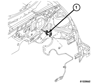
NOTE: The clutch master cylinder/hydraulic release system does not have its own reservoir. This system is supplied fluid from the brake master cylinder reservoir.
The clutch master cylinder (1) mounts to the dash panel and consists of a push rod, a piston and cylinder housing, an interconnecting hydraulic tube and a supply hose which connects to the brake master cylinder reservoir (1) for fluid supply.
OPERATION
When the clutch pedal is depressed, the push rod moves the piston in the master cylinder (2), displacing fluid through the hydraulic line and into the release bearing. The release bearing is forced into the fingers of the clutch diaphragm springs. As the fingers move, they release the clamping pressure on the clutch disc between the clutch pressure plate and the flywheel. The clutch becomes disengaged as this pressure is released.
When the clutch pedal is released, the system hydraulic pressure is released. This allows the force of the clutch diaphragm springs to return to their original position, re-clamping the clutch disc between the flywheel and the clutch pressure plate. Also, the release bearing and lever are forced to return, which reverses the movement of the hydraulic system and returns the pedal to its original position against the up-stop.
REMOVAL
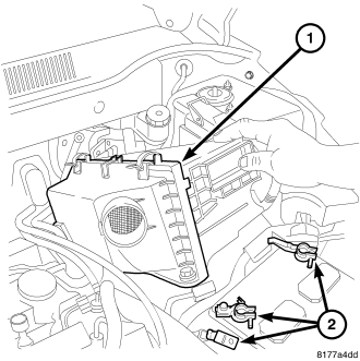
1. Remove the engine cover.
2. Remove air cleaner assembly (1).
3. Disconnect battery negative cable (2).
4. Remove lower instrument panel bezel.
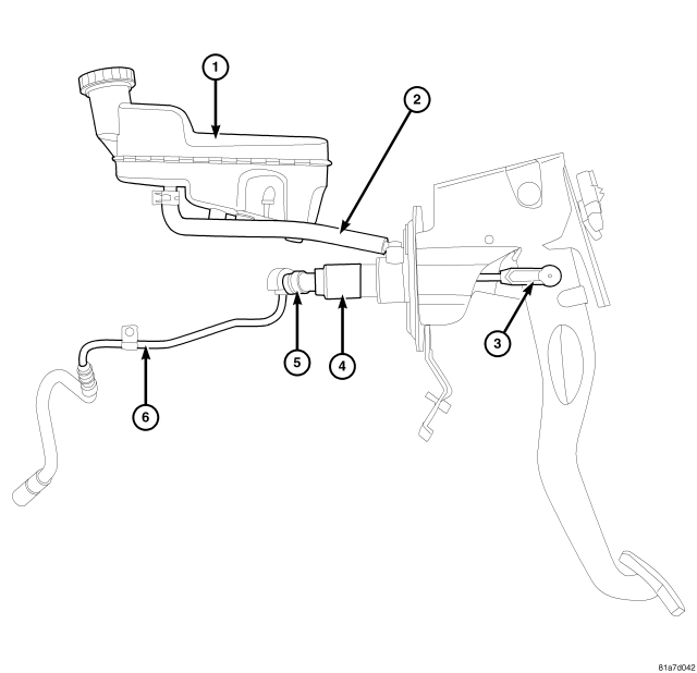
5. Disconnect the pushrod (3) at the clutch pedal.
6. Disconnect hydraulic supply tube at clutch slave cylinder by pulling retaining clip (5) then pulling out on tube. To completely drain clutch master cylinder and tubing, remove brake master cylinder cap band drain fluid into suitable container.
7. Disconnect clutch master cylinder supply line from brake master cylinder reservoir (1). Cap off or collect fluid spillage from reservoir port.
CAUTION: Use care when removing clutch master cylinder from engine compartment. Aggressive handling can result in a damaged hydraulic tube and improper clutch release operation upon reassembly.
CAUTION: Brake fluid will damage painted surfaces. If brake fluid is spilled on any painted surfaces, wash it off immediately with water.
8. Remove master cylinder assembly (1) from mounting position by turning 1/4 turn and carefully work hydraulic pipe from out of left rail retainer and engine compartment.
INSTALLATION
1. Install clutch master cylinder (1).
2. Insert tube into slave cylinder port and install retaining clip (5).
3. Connect clutch master cylinder supply hose (2) to brake master cylinder reservoir (1).
CAUTION: Due to clutch master cylinder design and placement, the master cylinder body traps a significant amount of air which does not purge by means of normal methods. It is necessary to position master cylinder body vertical, with pushrod pointing down, for about ten seconds to purge air trapped from end of cylinder. Failure to perform this step upon assembly will result in inadequate system bleeding and poor release system functionality.
4. Verify that brake master cylinder reservoir is full and cap is off.
5. Position clutch master cylinder body vertically, with pushrod pointing down, for about ten seconds to purge air trapped from end of cylinder.
6. Install clutch master cylinder body to dash panel and 1/4 turn to secure.
7. Connect clutch master cylinder rod to clutch pedal pin. An audible “click” should be heard.
8. Install lower instrument panel bezel.
9. Connect battery negative cable.
10. Install air cleaner assembly (1).
11. Verify that brake master cylinder reservoir is full. Top off with DOT 3 brake fluid if necessary.
12. Bleed clutch system (Refer to 6 - CLUTCH - STANDARD PROCEDURE).
13. Actuate clutch pedal a minimum of fifty times to allow any air ingested into the system to vent to the master cylinder reservoir. If residual air becomes trapped in the system, it is necessary to bleed the clutch hydraulic system.
14. Verify proper clutch release system operation.