P0716-INPUT SPEED SENSOR 1 CIRCUIT PERFORMANCE
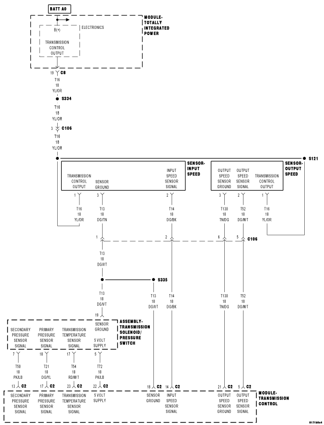
For a complete wiring diagram Refer to Section 8W.
Theory of Operation
The transmission system uses two speed sensors. One is used to measure input rpm (primary pulley) and one to measure output rpm (secondary pulley).
The Input Speed sensor detects the primary pulley rpm by the use of a three-wire magnetic pickup devices that generates a square wave signal as rotation occurs and is monitored by the Transmission Control Module (TCM). These inputs are essential for proper transmission operation.
- When Monitored:
Ignition on, engine running with the transmission in a valid forward gear.
System voltage between 9.0 and 16.0 volts
Vehicle speed greater than 10 Km/h (6 mph).
Accelerator Pedal Position (APP) greater than 12.5%.
Engine rpm greater than 450 rpm with TCC lock-up enabled.
No DTCs from the following:
- TCC Solenoid
- Lock-up solenoid
- Step motor
- Input or Output Speed Sensor No Signal
- Transmission Range Sensor (TRS)
- Sensor Ground
- CAN
- Set Condition:
All the below conditions must be present for the period of 5 seconds for the DTC to set:
- Engine speed minus the primary speed is greater than 1000 rpm.
- Secondary speed multiplied by the estimated ratio, minus the Primary speed is greater than 1000 rpm.
- Engine speed minus the Secondary speed, multiplied by the estimated ratio is less than 1000 rpm.
| Possible Causes |
| ENGINE CAM OR CRANK DTCS PRESENT |
| DIRTY OR DAMAGED INPUT SPEED SENSOR |
| (T16) TRANSMISSION CONTROL OUTPUT CIRCUIT HIGH RESISTANCE |
| (T14) INPUT SPEED SENSOR SIGNAL CIRCUIT SHORT TO VOLTAGE |
| (T14) INPUT SPEED SENSOR SIGNAL CIRCUIT HIGH RESISTANCE |
| INPUT SPEED SENSOR |
| TORQUE CONVERTER CLUTCH |
| TRANSMISSION CONTROL MODULE |
Always perform the CVT Pre-Diagnostic Troubleshooting procedure before proceeding. (Refer to 21 - TRANSMISSION/TRANSAXLE/AUTOMATIC - CVT - STANDARD PROCEDURE)
Diagnostic Test
1. CHECK TO SEE IF THE DTC IS ACTIVEWith the scan tool, read Transmission DTCs.
Is the status Active for this DTC or is the STARTS SINCE SET counter 2 or less?
Yes
- Go To 2
No
- Go To 10
2. CHECK FOR ENGINE CAM OR CRANK SENSOR DTCS
With the scan tool, check engine DTCs.
Are there any Engine Cam or Crank sensor DTCs present?
Yes
- Refer to the engine category and perform the appropriate symptom(s).
- Perform CVT VERIFICATION TEST. (Refer to 21 - TRANSMISSION/TRANSAXLE/AUTOMATIC - CVT - STANDARD PROCEDURE)
No
- Go To 3
3. CHECK THE (T16) TRANSMISSION CONTROL OUTPUT CIRCUIT FOR AN OPEN (HIGH RESISTANCE)

Disconnect the Input Speed Sensor harness connector.
Ignition on, engine not running
With the scan tool under TIPM, actuate the Transmission.
Using a 12-volt test light connected to ground, check the (T16) Transmission Control Output circuit at the Input Speed Sensor harness connector.
NOTE: The test light must illuminate brightly. Compare the brightness to that of a direct connection to the battery.
Does the test light illuminate brightly?
Yes
- Go To 4
No
- Repair the (T16) Transmission Control Output circuit for an open or high resistance.
- Perform CVT VERIFICATION TEST. (Refer to 21 - TRANSMISSION/TRANSAXLE/AUTOMATIC - CVT - STANDARD PROCEDURE)
4. CHECK THE (T14) INPUT SPEED SENSOR SIGNAL CIRCUIT
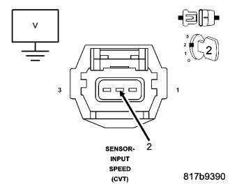
With the scan tool under TIPM, stop the Transmission actuator.
Turn the ignition off, wait 5 seconds, then turn the ignition on.
Measure the voltage of the (T14) Input Speed Sensor Signal circuit.
Pick the answer that best matches your findings:
Voltage above 5.5 volts
- Go To 6
Voltage below 4.5 volts
- Go To 5
Voltage between 4.5 and 5.5 volts
- Go To 7
5. CHECK THE (T14) INPUT SPEED SENSOR SIGNAL CIRCUIT FOR AN OPEN (HIGH RESISTANCE)
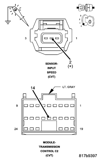
Turn the ignition off to the lock position.
Disconnect the TCM C2 harness connector.
Connect a jumper wire between the (T14) Input Speed Sensor Signal circuit in the Input Speed Sensor harness connector and B(+).
Using a 12-volt test light connected to ground, check the (T14) Input Speed Sensor Signal circuit in the TCM C2 harness connector.
NOTE: The test light must illuminate brightly. Compare the brightness to that of a direct connection to the battery.
Does the test light illuminate brightly?
Yes
- Using the schematics as a guide, check the Transmission Control Module (TCM) terminals for corrosion, damage, or terminal push out. Pay particular attention to all power and ground circuits. Check for any Service Bulletins for possible causes that may apply. If no problems are found, replace the TCM per the Service Information.
- Perform CVT VERIFICATION TEST. (Refer to 21 - TRANSMISSION/TRANSAXLE/AUTOMATIC - CVT - STANDARD PROCEDURE)
No
- Repair the (T14) Input Speed Sensor Signal circuit for an open or high resistance.
- Perform CVT VERIFICATION TEST. (Refer to 21 - TRANSMISSION/TRANSAXLE/AUTOMATIC - CVT - STANDARD PROCEDURE)
6. CHECK THE (T14) INPUT SPEED SENSOR SIGNAL CIRCUIT FOR A SHORT TO VOLTAGE
Turn the ignition off to the lock position.
Disconnect the TCM C2 harness connector.
Ignition on, engine not running
Measure the voltage of the (T14) Input Speed Sensor Signal circuit.
Is the voltage above 0.2 volts?
Yes
- Repair the (T14) Input Speed Sensor Signal circuit for a short to voltage.
- Perform CVT VERIFICATION TEST. (Refer to 21 - TRANSMISSION/TRANSAXLE/AUTOMATIC - CVT - STANDARD PROCEDURE)
No
- Using the schematics as a guide, check the Transmission Control Module (TCM) terminals for corrosion, damage, or terminal push out. Pay particular attention to all power and ground circuits. Check for any Service Bulletins for possible causes that may apply. If no problems are found, replace the TCM per the Service Information.
- Perform CVT VERIFICATION TEST. (Refer to 21 - TRANSMISSION/TRANSAXLE/AUTOMATIC - CVT - STANDARD PROCEDURE)
7. CHECK THE TORQUE CONVERTER
Turn the ignition off to the lock position.
Reinstall all components and reconnect all previously disconnected harness connectors.
Ignition on, engine not running
With the scan tool, erase all Transmission DTCs.
Test drive the vehicle to speeds allowing the Torque Converter to obtain lock-up. Note the Engine rpm compared to the Transmission Input rpm.
Did the difference between the Engine rpm and the Transmission Input rpm differ over 1000 rpm?
Yes
- Go To 8
No
- Go To 9
8. CHECK THE INPUT SPEED SENSOR
Turn the ignition off to the lock position.
Remove the Input Speed Sensor per the Service Information.
Check the Input Speed Sensor for any debris buildup or damage.
Did the Input Speed Sensor show any signs of debris buildup or damage?
Yes
- If there is a debris build up, clean the Output Speed Sensor as necessary and reinstall. If damaged or questionable in condition, replace the Input Speed Sensor.
- Perform CVT VERIFICATION TEST. (Refer to 21 - TRANSMISSION/TRANSAXLE/AUTOMATIC - CVT - STANDARD PROCEDURE)
No
- Replace the Torque Converter per the Service Information.
- Perform CVT VERIFICATION TEST. (Refer to 21 - TRANSMISSION/TRANSAXLE/AUTOMATIC - CVT - STANDARD PROCEDURE)
9. CHECK IF THE DTC RESETS
Did the DTC P0716-INPUT SPEED SENSOR 1 CIRCUIT PERFORMANCE reset during the test drive?
Yes
- Using the schematics as a guide, check the Transmission Control Module (TCM) terminals for corrosion, damage, or terminal push out. Pay particular attention to all power and ground circuits. Check for any Service Bulletins for possible causes that may apply. If no problems are found, replace the TCM per the Service Information.
- Perform CVT VERIFICATION TEST. (Refer to 21 - TRANSMISSION/TRANSAXLE/AUTOMATIC - CVT - STANDARD PROCEDURE)
No
- Go To 10
10. INTERMITTENT WIRING AND CONNECTORS
The conditions necessary to set this DTC are not present at this time.
Using the schematics as a guide, inspect the wiring and connectors specific to this circuit.
Wiggle the wires while checking for shorted and open circuits.
Check for any Service Bulletins for possible causes that may apply.
Were there any problems found?
Yes
- Repair as necessary.
- Perform CVT VERIFICATION TEST. (Refer to 21 - TRANSMISSION/TRANSAXLE/AUTOMATIC - CVT - STANDARD PROCEDURE)
No
- Test Complete.