P0777-SECONDARY PRESSURE SOLENOID STUCK ON (LOW PRESSURE)
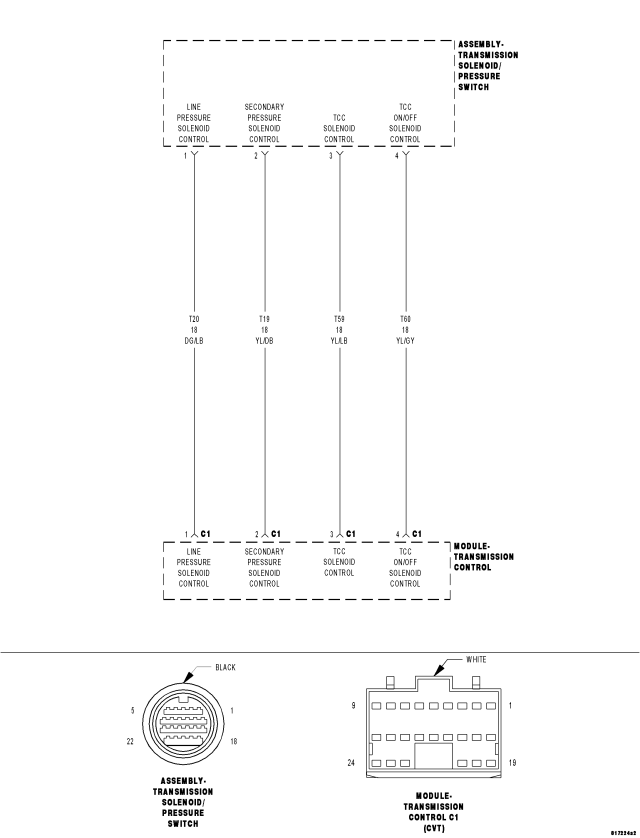
For a complete wiring diagram Refer to Section 8W.
Theory of Operation
The Transmission Control Module (TCM) monitors the secondary line pressure (secondary pulley pressure) from the secondary pressure sensor. The TCM compares the actual secondary line pressure to the target (desired) line pressure. Failure to match the target line pressure over a given time will set the DTC.
- When Monitored:
Ignition on, engine running with the transmission not in neutral or park.
Transmission fluid temperature greater than -20° C (-4° F).
Brake Switch in the OFF mode.
Change rate of vehicle speed greater than 24 Km/h (15 mph).
Change rate of accelerator pedal position less than ± 6.25%.
Engine rpm greater than 450 rpm with a transmission fluid temperature greater than 20° C (68° F)
No active DTCs from the following:
- Line Pressure Solenoid
- Primary or Secondary Pressure Sensor
- Step Motor
- Secondary Solenoid electrical
- Input and Output Speed Sensor
- CAN Bus
- Set Condition:
When the secondary pressure goes down gradually below a predetermined value during a drive cycle. The DTC could be due to the failure of the secondary pressure control system, secondary pressure solenoid performance or line pressure solenoid. There are two possible setting conditions to set this DTC.
Condition one:
- Target secondary pressure minus the measured secondary pressure is greater than 0.25 MPa (36 psi) for two consecutive instances of a problem identification for the period of 1.5 seconds within a 30 second interval.
Condition two:
- Target secondary pressure minus the measured secondary pressure is greater than 2.0 MPa (291 psi) for the period of 800 msec.
| Possible Causes |
| (T50) SECONDARY PRESSURE SENSOR SIGNAL CIRCUIT |
| LINE PRESSURE SOLENOID |
| SECONDARY PRESSURE SENSOR |
| SECONDARY PRESSURE SOLENOID |
| SECONDARY PRESSURE CONTROL SYSTEM |
| TRANSMISSION CONTROL MODULE |
Always perform the CVT Pre-Diagnostic Troubleshooting procedure before proceeding. (Refer to 21 - TRANSMISSION/TRANSAXLE/AUTOMATIC - CVT - STANDARD PROCEDURE)
Diagnostic Test
1. CHECK IF THE DTC IS ACTIVEWith the scan tool, read Transmission DTCs.
Is the status Active for this DTC or is the STARTS SINCE SET counter 2 or less?
Yes
- Go To 2
No
- Go To 7
2. CHECK LINE PRESSURE
| Engine rpm | Line Pressure |
| Idle | 750 kPa (108.8 psi) ± 400 kPa (58 psi) |
| 2.0L – 2500 to 3000 rpm | 5300 - 5700 kPa (768.5 - 826.5 psi) ± 400 kPa (58 psi) |
| 2.4L – 2600 to 3100 rpm |
Start the engine and warm the transmission to 50 - 80° C (122 - 174° F).
Turn the ignition off to the lock position.
Install an appropriate pressure gauge in the Line Pressure test port per the Service Information.
WARNING: The CV Transmission can generate a line pressure up to 1800 psi. Failure to use recommended test equipment referred to by the Service Information can result in personal injury or death.
With the scan tool, erase Transmission DTCs.
WARNING: Apply the parking brake. Failure to follow these instructions can result in personal injury or death.
With the brakes firmly applied, start the engine allow to idle and shift the transmission into Reverse, Drive and Low while recording the scan tool Line pressure reading and the pressure gauge reading in each shift lever position.
With the brakes still firmly applied, raise the engine rpm between 2700 - 3250 rpm and shift the transmission into Reverse, Drive and Low while recording the scan tool line pressure reading and the pressure gauge reading in each shift lever position.
CAUTION: Do not hold the engine rpm between 2700 - 3250 rpm for more than 5 seconds in any given shift position. If the 5 second threshold is exceeded, transmission damage can occur. Allow to idle in neutral between shifts for at least 15 to 20 seconds to allow transmission fluid to cool.
Do the gauge readings fall into the desired pressure ranges?
Yes
- Go To 4
No
- Go To 3
3. VERIFY PROBLEM
| ENGINE RPM | LINE PRESSURE CONDITION DETECTED | POSSIBLE CAUSES BUT NOT JUST LIMITED TO THESE |
| Idle speed | Low for all shift lever positions | Oil Pump Wear |
| Pressure Regulator Valve for plug sticking or spring fatigue | ||
| Oil filter, oil pump, pressure regulator valve passage oil leak | ||
| Engine idle speed too low | ||
| Only low for a specific position | Oil pressure leak in a passage or component related to the position after the pressure is distributed by the manual valve | |
| High | TP or APP sensor signal malfunction | |
| CVT fluid temperature sensor malfunction | ||
| Line pressure solenoid sticking in the off state, filter plugged, cut line | ||
| Pressure regulator valve or plug sticking | ||
| Engine rpm between 2700 and 3250 rpm | Line pressure does not rise above the line pressure at idle | TP or APP sensor signal malfunction |
| Line pressure solenoid sticking in the on state, filter plugged | ||
| Pressure regulator valve or plug sticking | ||
| Transmission Control Module (TCM) | ||
| Oil pump weak or worn | ||
| Line Pressure rises but does not reach desired level | TP or APP sensor signal malfunction | |
| Line pressure solenoid sticking in the off state, filter plugged, cut line | ||
| Pressure regulator valve or plug sticking | ||
| Oil pump weak or worn | ||
| Line pressure is low in only one shift lever position | Oil pressure leak in a passage or component related to the position after the pressure is distributed by the manual valve |
Use the above chart to help identify the possible cause.
NOTE: There may be other possible causes besides those listed on the above chart. Review any Service Bulletins and refer to the Service Information for any additional possible causes that may apply.
View repair
Repair
- Replace or repair the CV Transmission as necessary per the Service Information
- Perform CVT VERIFICATION TEST. (Refer to 21 - TRANSMISSION/TRANSAXLE/AUTOMATIC - CVT - STANDARD PROCEDURE)
4. CHECK THE SECONDARY PRESSURE
Turn the ignition off to the lock position.
Disconnect the pressure gauge from the Line Pressure test port and reinstall the test port plug.
Install the pressure gauge in the Secondary Pressure test port per the Service Information.
With the scan tool, erase Transmission DTCs.
WARNING: Apply the parking brake. Failure to follow these instructions can result in personal injury or death.
With the brakes firmly applied, start the engine allow to idle and shift the transmission into Reverse, Drive and Low while comparing the Secondary Pressure gauge reading to the scan tool Secondary Pressure reading in each shift lever position and record your findings.
With the brakes still firmly applied, raise the engine rpm between 2700 - 3250 rpm and shift the transmission into Reverse, Drive and Low while comparing the gauge Secondary Pressure to the scan tool Secondary Pressure in each shift lever position and record your findings.
CAUTION: Do not hold the engine rpm between 2700 - 3250 rpm for more than 5 seconds in any given shift position. If the 5 second threshold is exceeded, transmission damage can occur. Allow to idle in neutral between shifts for at least 15 to 20 seconds to allow transmission fluid to cool.
Does the Secondary Pressure gauge readings match the scan tool readings in all of the above procedures?
Yes
- Replace or repair the CV Transmission as necessary per the Service Information for components related to the Secondary Pressure Control System.
- Perform CVT VERIFICATION TEST. (Refer to 21 - TRANSMISSION/TRANSAXLE/AUTOMATIC - CVT - STANDARD PROCEDURE)
No
- Go To 5
5. CHECK THE SECONDARY PRESSURE SENSOR
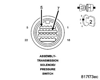
Turn the ignition off to the lock position.
Disconnect the pressure gauge from the Secondary Pressure test port and reinstall the test port plug.
Disconnect the Transmission Solenoid/Pressure Switch Assembly harness connector.
Connect a jumper wire between the (T50) Secondary Pressure Sensor Signal circuit and the (T72) 5-volt Supply circuit in the Transmission Solenoid/Pressure Switch Assembly harness connector.
Ignition on, engine not running.
With the scan tool read the Secondary Pressure voltage.
Is the voltage between 4.5 and 5.5 volts?
Yes
- Replace the CVT or the Secondary Pressure Sensor (Valve Body) per the Service Information.
- Perform CVT VERIFICATION TEST. (Refer to 21 - TRANSMISSION/TRANSAXLE/AUTOMATIC - CVT - STANDARD PROCEDURE)
No
- Go To 6
6. CHECK THE (T21) PRIMARY PRESSURE SENSOR SIGNAL CIRCUIT FOR HIGH RESISTANCE
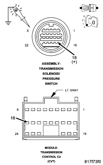
Turn the ignition off to the lock position.
Disconnect the TCM C2 harness connector.
Connect a jumper wire between the B(+) and the (T21) Primary Pressure Sensor Signal circuit in the Transmission Solenoid/Pressure Switch harness connector.
Using a 12-volt test light connected to ground, check the (T21) Primary Pressure Sensor Signal circuit in the TCM C2 harness connector.
NOTE: The test light must illuminate brightly. Compare the brightness to that of a direct connection to the battery.
Does the test light illuminate brightly?
Yes
- Using the schematics as a guide, check the Transmission Control Module (TCM) terminals for corrosion, damage, or terminal push out. Pay particular attention to all power and ground circuits. Check for any Service Bulletins for possible causes that may apply. If no problems are found, replace the TCM per the Service Information.
- Perform CVT VERIFICATION TEST. (Refer to 21 - TRANSMISSION/TRANSAXLE/AUTOMATIC - CVT - STANDARD PROCEDURE)
No
- Repair the (T21) Primary Pressure Sensor Signal circuit for an open (high resistance).
- Perform CVT VERIFICATION TEST. (Refer to 21 - TRANSMISSION/TRANSAXLE/AUTOMATIC - CVT - STANDARD PROCEDURE)
7. INTERMITTENT WIRING AND CONNECTORS
The conditions necessary to set this DTC are not present at this time.
Using the schematics as a guide, inspect the wiring and connectors specific to this circuit.
Wiggle the wires while checking for shorted and open circuits.
Were there any problems found?
Yes
- Repair as necessary.
- Perform CVT VERIFICATION TEST. (Refer to 21 - TRANSMISSION/TRANSAXLE/AUTOMATIC - CVT - STANDARD PROCEDURE)
No
- Test Complete.