P128E-TCM POWER CONTROL CIRCUIT 2 OVERCURRENT - TIPM
For a complete wiring diagram Refer to Section 8W.
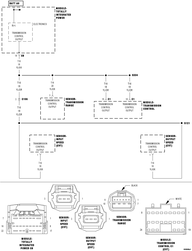
- When Monitored:
With the ignition on. Battery voltage greater than 10 volts.
- Set Condition:
An overcurrent condition is detected in the TCM Power Control circuit. One Trip Fault. Three good trips to turn off the MIL.
| Possible Causes |
| INPUT OR OUTPUT SPEED SENSOR |
| TRANSMISSION RANGE SENSOR |
| TRANSMISSION CONTROL MODULE |
| TOTALLY INTEGRATED POWER MODULE (TIPM) |
Always perform the CVT Pre-Diagnostic Troubleshooting procedure before proceeding. (Refer to 21 - TRANSMISSION/TRANSAXLE/AUTOMATIC - CVT - STANDARD PROCEDURE)
Diagnostic Test
1. CHECK IF THE DTC IS ACTIVEIgnition on, engine not running.
With a scan tool, read TIPM DTCs.
Is the DTC active at this time?
Yes
- Go To 2
No
- Go To 4
2. CHECK IF THE DTC IS ACTIVE
Ignition on, engine not running.
With a scan tool, read Transmission DTCs.
Are there any Input or Output Speed Sensor or Transmission Range Sensor (TRS) DTCs present?
Yes
- Refer to the Transmission category and perform the appropriate symptom(s).
- Perform CVT VERIFICATION TEST. (Refer to 21 - TRANSMISSION/TRANSAXLE/AUTOMATIC - CVT - STANDARD PROCEDURE)
No
- Go To 3
3. CHECK THE TCM
Disconnect the amp meter from the TIPM C10 harness connector and battery positive.
Disconnect the TCM C1 harness connector.
Connect the positive probe of an ammeter to battery positive and connect the negative probe to the (T16) Transmission Control Output circuit in the TIPM C10 harness connector.
Read the amperage on the ammeter.
Does the amperage read below 2.0 amps?
Yes
- Using the schematics as a guide, check the Transmission Control Module (TCM) terminals for corrosion, damage, or terminal push out. Pay particular attention to all power and ground circuits. If no problems are found, replace the TCM per the Service Information.
- Perform CVT VERIFICATION TEST. (Refer to 21 - TRANSMISSION/TRANSAXLE/AUTOMATIC - CVT - STANDARD PROCEDURE)
No
- Replace the Totally Integrated Control Module per the Service Information.
- Perform CVT VERIFICATION TEST. (Refer to 21 - TRANSMISSION/TRANSAXLE/AUTOMATIC - CVT - STANDARD PROCEDURE)
4. INTERMITTENT WIRING AND CONNECTORS
The conditions necessary to set this DTC are not present at this time.
Using the schematics as a guide, inspect the wiring and connectors specific to this circuit.
Wiggle the wires while checking for shorted and open circuits.
Were there any problems found?
Yes
- Repair as necessary.
- Perform CVT VERIFICATION TEST. (Refer to 21 - TRANSMISSION/TRANSAXLE/AUTOMATIC - CVT - STANDARD PROCEDURE)
No
- Test Complete.