P1729-TRANSMISSION RATIO CONTROL CIRCUIT
For a complete wiring diagram Refer to Section 8W.
Theory of Operation
The Transmission Control Module monitors and controls the gear ratio by the use of a Step motor that transfers electrical power to mechanical movement. The rationality is a continuous test that monitors the Step motor movement. If the Step motor ON/OFF status does not match the TCM requested ON/OFF status a DTC will set.
- When Monitored:
Ignition on with a system voltage between 9.0 and 16.0 volts.
- Set Condition:
If the Step motor ON/OFF status does not match the TCM requested ON/OFF status for the period of 200 msec the DTC will set. It takes two consecutive problem identification trips to illuminate the MIL.
| Possible Causes |
| (T314) A, (T315) B, (T316) C, AND/OR (T317) D STEP MOTOR CONTROL CIRCUIT(S) SHORT TO VOLTAGE |
| (T314) A, (T315) B, (T316) C, AND/OR (T317) D STEP MOTOR CONTROL CIRCUIT(S) OPEN |
| (T314) A, (T315) B, (T316) C, AND/OR (T317) D STEP MOTOR CONTROL CIRCUIT(S) SHORT TO GROUND |
| STEP MOTOR |
| TRANSMISSION CONTROL MODULE |
Always perform the CVT Pre-Diagnostic Troubleshooting procedure before proceeding. (Refer to 21 - TRANSMISSION/TRANSAXLE/AUTOMATIC - CVT - STANDARD PROCEDURE)
Diagnostic Test
1. CHECK TO SEE IF THE DTC IS ACTIVEWith the scan tool, read Transmission DTCs.
Is the status Active for this DTC or is the STARTS SINCE SET counter 2 or less?
Yes
- Go To 2
No
- Go To 6
2. CHECK THE (T314) A, (T315) B, (T316) C, AND (T317) D STEP MOTOR CONTROL CIRCUIT(S) FOR A SHORT TO VOLTAGE
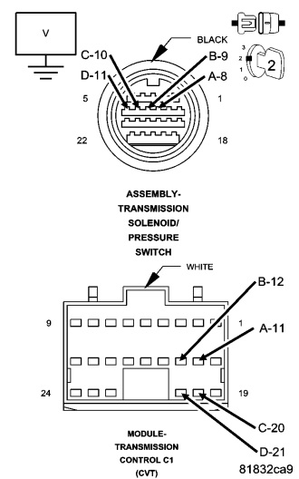
Turn the ignition off to the lock position.
Disconnect the TCM C1 and C2 harness connectors.
Disconnect the Transmission Solenoid/Pressure Switch Assembly harness connector.
Ignition on, engine not running.
Measure separately the voltage of the (T314) A, (T315) B, (T316) C, and (T317) D Step Motor Control circuits.
Is the voltage above .05 volts for any of the Step Motor Control circuits?
Yes
- Repair the (T314) A, (T315) B, (T316) C, and/or (T317) D Step Motor Control circuit(s) for a short to voltage.
- Perform CVT VERIFICATION TEST. (Refer to 21 - TRANSMISSION/TRANSAXLE/AUTOMATIC - CVT - STANDARD PROCEDURE)
No
- Go To 3
3. CHECK THE (T314) A, (T315) B, (T316) C, AND (T317) D STEP MOTOR CONTROL CIRCUIT(S) FOR AN OPEN
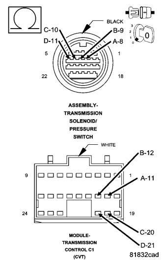
Turn the ignition off to the lock position.
Measure separately the resistance of the (T314) A, (T315) B, (T316) C, and (T317) D Step Motor Control circuits between the TCM C1 harness connector and the Transmission Solenoid/Pressure Switch harness connector.
Is the resistance above 5.0 ohms for any of the Step Motor Control circuits?
Yes
- Repair the (T314) A, (T315) B, (T316) C, and/or (T317) D Step Motor Control circuit(s) for an open.
- Perform CVT VERIFICATION TEST. (Refer to 21 - TRANSMISSION/TRANSAXLE/AUTOMATIC - CVT - STANDARD PROCEDURE)
No
- Go To 4
4. CHECK THE (T314) A, (T315) B, (T316) C, AND (T317) D STEP MOTOR CONTROL CIRCUIT(S) FOR A SHORT TO GROUND
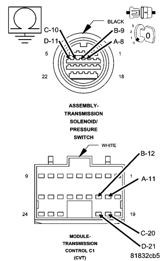
Measure separately the resistance between ground and the (T314) A, (T315) B, (T316) C, and (T317) D Step Motor Control circuits.
Is the resistance below 5.0 ohms for any of the Step Motor Control circuits?
Yes
- Repair the (T314) A, (T315) B, (T316) C, and/or (T317) D Step Motor Control circuit(s) for a short to ground.
- Perform CVT VERIFICATION TEST. (Refer to 21 - TRANSMISSION/TRANSAXLE/AUTOMATIC - CVT - STANDARD PROCEDURE)
No
- Go To 5
5. TRANSMISSION CONTROL MODULE
Replace the Transmission Control Module per the Service Information. Perform CVT VERIFICATION TEST. (Refer to 21 - TRANSMISSION/TRANSAXLE/AUTOMATIC - CVT - STANDARD PROCEDURE)
During the verification test did the DTC reset?
Yes
- Replace or repair the CV Transmission (Step Motor) per the Service Information.
- Perform CVT VERIFICATION TEST. (Refer to 21 - TRANSMISSION/TRANSAXLE/AUTOMATIC - CVT - STANDARD PROCEDURE)
No
- Test Complete.
6. INTERMITTENT WIRING AND CONNECTORS
The conditions necessary to set this DTC are not present at this time.
Using the schematics as a guide, inspect the wiring and connectors specific to this circuit.
Wiggle the wires while checking for shorted and open circuits.
Were there any problems found?
Yes
- Repair as necessary.
- Perform CVT VERIFICATION TEST. (Refer to 21 - TRANSMISSION/TRANSAXLE/AUTOMATIC - CVT - STANDARD PROCEDURE)
No
- Test Complete.