BODY-VALVE
OPERATION
| Component | Function |
| Torque converter regulator valve | Optimizes the supply pressure for the torque converter depending on driving conditions. |
| Clutch regulator valve | Adjusts the clutch operating pressure depending on operating conditions. |
| Pressure regulator valve | Optimizes the discharge pressure (line pressure) from the oil pump depending on driving conditions. |
| Shift control valve | Controls flow-in/out of line pressure to/from the primary pulley depending on the stroke difference between the stepping motor and the primary pulley. |
| Lock-up/Select switch solenoid valve | Switches use of the lock-up solenoid control pressure between applying/releasing lock-up and engaging/releasing the forward/reverse clutch (the forward clutch and the reverse brake). |
| Select switch valve | Switches use of the lock-up solenoid control pressure between applying/releasing lock-up and engaging/releasing the forward/reverse clutch (the forward clutch and the reverse brake). |
| Line pressure solenoid valve | Controls the line pressure control valve. |
| Lock-up solenoid valve | Controls the lock-up control valve. |
| Lock-up/Select switch solenoid valve | Controls the select switching valve. |
| Stepping motor | Controls the pulley ratio. |
| Secondary valve | Reduces the line pressure and adjusts the secondary pressure. |
| Select control valve | Engages when making a selection. Adjusts the forward clutch pressure and the reverse brake pressure. |
| Lock-up control valve | Adjusts engaging/releasing pressure for the torque converter. |
| Secondary pressure solenoid valve | Controls flow-in/out of line pressure to/from the secondary pulley depending on driving conditions. |
REMOVAL
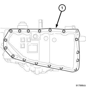
1. Remove the bolts holding the oil pan (1) to the transaxle case.
2. Remove the oil pan from the transaxle case.
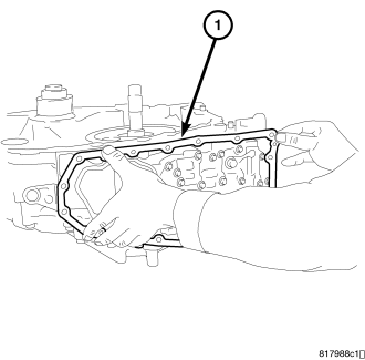
3. Remove the oil pan gasket (1) from the transaxle case.
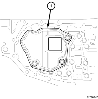
4. Remove the bolts holding the oil strainer (1) to the valve body.
5. Remove the oil strainer.
6. Remove and discard the oil strainer o-ring.
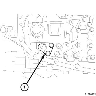
7. Remove the bolts holding the bracket (1) to the valve body assembly.
8. Remove the bracket from the valve body assembly.
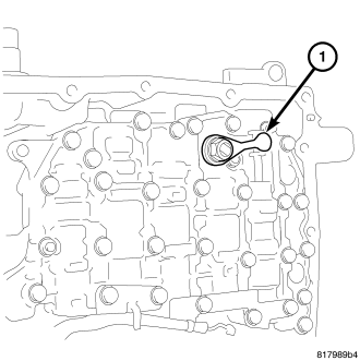
9. Remove the nut holding the manual lever (1) to the manual shaft.
10. Remove the manual lever from the manual shaft.
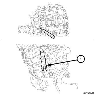
CAUTION: Tilt the valve body assembly away from the transaxle case on the manual shaft side to ease removal. Pay attention to completely remove the terminal body from the transaxle case.
11. Remove the valve body assembly from the transaxle case as follows:
a. Insert a 75 mm (3 in.) long 3 mm (0.118 in.) wide rod or wire into the linkage stopper hole of the valve body assembly to fix the pulley ratio linkage (1).
b. Remove the bolts holding the valve body assembly to the transaxle case.
c. Remove the valve body assembly from the transaxle case.
DISASSEMBLY
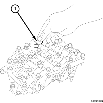
1. Remove and discard the bushing (1) from the valve body.
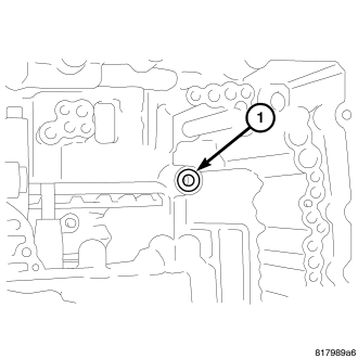
2. Remove and discard the lip seal (1) from the transaxle case.
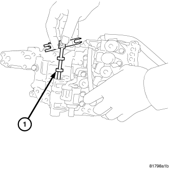
CAUTION: Do not drop the pulley ratio linkage.
3. Remove the pulley ratio linkage (1) from the valve body.
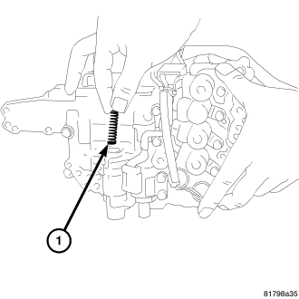
4. Remove the return spring (1) from the valve body.
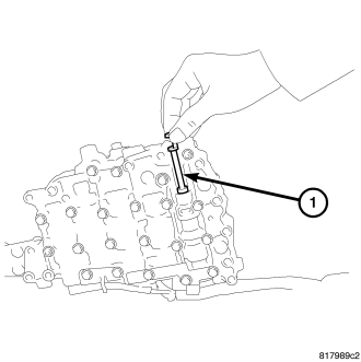
CAUTION: Do not drop the manual valve.
5. Remove the manual valve (1) from the valve body.
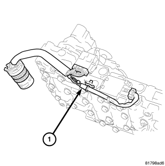
6. Remove the valve body harness (1) from the valve body.
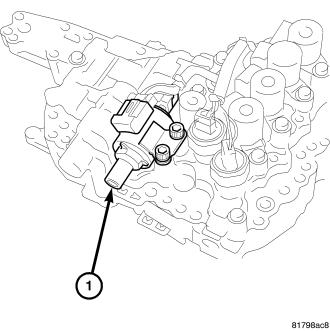
7. Remove the stepping motor (1) from the valve body.
ASSEMBLY
CAUTION: Do not re-use the lip seal. Apply CVT fluid when installing the lip seal.
1. Install the new lip seal (1) into the transaxle case.
2. Install the stepping motor (1) onto the control valve body. Install and tighten the mounting bolts to 8 N·m (70 in. lbs.).
3. Install the valve body harness (1) onto the control valve body.
CAUTION: Ensure the manual valve is free of dirt, lint or other debris. Apply CVT fluid when installing the manual valve.
4. Install the manual valve (1) into the control valve body.
5. Install the return spring (1) into the control valve body.
CAUTION: Apply CVT fluid when installing the pulley ratio linkage.
6. Hook the pawl of the pulley ratio linkage (1) onto the stepping motor and install it on the control valve.
INSTALLATION
1. To install the control valve body assembly on to the transaxle case, insert a 75 mm (3 in.) long 3 mm (0.118 in.) wide rod or wire into the linkage stopper hole of the control valve assembly to set the pulley ratio linkage (1) in position.
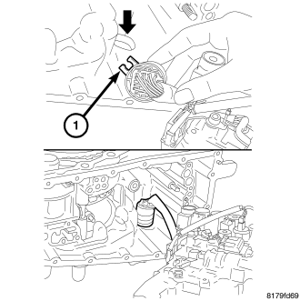
2. Position the locating tab (1) of the terminal body as shown and install the terminal body into the transaxle case.
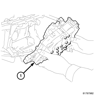
3. Install the control valve assembly (1) up from the bottom side and install it into the transaxle case.
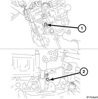
4. Align the notch (1) of the pulley ratio linkage with the sheave position sensor (2).
CAUTION: Apply CVT fluid when installing the bushing.
5. Install the bushing (1) into the control valve assembly.
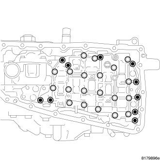
6. Tighten the mounting bolts of the control valve body assembly to 8 N·m (70 in. lbs).
7. Install the manual lever (1) onto the manual shaft. Install and tighten the mounting nut to 22 N·m (16 in. lbs.).
8. Install the bracket (1) onto the control valve assembly. Install and tighten the mounting bolts to 8 N·m (70 in. lbs.).
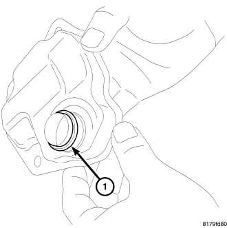
CAUTION: Do not re-use the o-ring. Apply CVT fluid when installing the o-ring.
9. Install the new o-ring (1) onto the new oil strainer.
10. Install the new oil strainer (1) onto the control valve assembly. Install and tighten the mounting bolts to 8 N·m (70 in. lbs.).
CAUTION: Do not re-use the oil pan gasket. Remove any moisture, oil, and used gasket material from the surface where the new gasket is to be installed. When installing the oil pan gasket, align the dowel pin with the dowel pin hole in the oil pan gasket.
11. Install the oil pan gasket (1) onto the transaxle case.
CAUTION: When installing the oil pan, align the dowel pin of the transaxle case with the dowel pin hole of the oil pan.
12. Install the oil pan on the transaxle case (1). Install and tighten the mounting bolts to 8 N·m (70 in. lbs.).
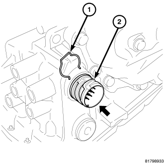
13. Install the snap ring (1) onto the terminal body.
14. Fill transmission with the required fluid. (Refer to 21 - TRANSMISSION/TRANSAXLE/AUTOMATIC - CVT/FLUID - STANDARD PROCEDURE)