MASTER CYLINDER
DESCRIPTION
The master cylinder used on this vehicle is a Plunger II design supplied by Continental Teves. The bore diameter for all applications is 20.6 mm (0.812 in.).
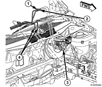
All master cylinders (3) are a two-outlet design and the brake tubes from these primary and secondary outlet ports lead directly to the Integrated Control Unit (ICU) before going to each wheel brake.
The master cylinder body is an anodized aluminum casting. It has a machined bore to accept the master cylinder pistons and also has threaded ports with seats for hydraulic brake tube connections.
The master cylinder has the brake fluid reservoir mounted on top of it which gravity feeds brake fluid to the master cylinder when it is required. On manual transmission model vehicles the brake fluid reservoir also feeds the clutch hydraulic circuit. The reservoir is made of see-through plastic and it houses the brake fluid level switch. A removable brake fluid level switch is mounted in the right side.
OPERATION
When the brake pedal is pressed, the master cylinder primary and secondary pistons apply brake pressure through the ABS Integrated Control Unit (ICU) and chassis brake tubes to each brake assembly. The brake fluid reservoir supplies the brake hydraulic system with the necessary fluid to operate properly.
ABS (ESP) equipped master cylinder outlet ports supply hydraulic pressure to the ABS ICU where it is distributed to the individual wheel brakes.
The master cylinder reservoir cap diaphragm is slit to allow atmospheric pressure to equalize on both sides of the diaphragm.
DISASSEMBLY
1. Clean the master cylinder housing and brake fluid reservoir. Use only Mopar® Brake Parts Cleaner or equivalent.
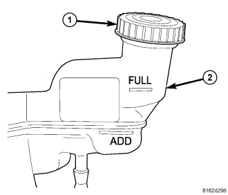
2. Remove the brake fluid reservoir cap (1). Using a syringe or equivalent type tool, empty as much brake fluid as possible from the reservoir.
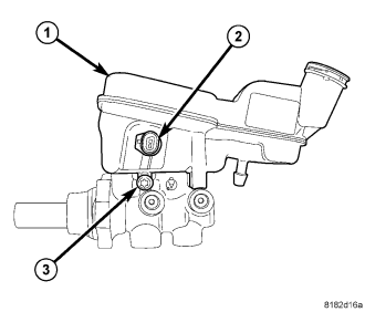
CAUTION: When removing the fluid reservoir (1) from the master cylinder, do not attempt to pry it off using any type of tool. This can damage the fluid reservoir or master cylinder housing.
3. Remove the screw (3) fastening the fluid reservoir (1) to the master cylinder housing.
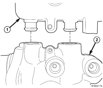
4. Pull the reservoir (1) straight up and remove it from the grommet seals in master cylinder housing (2).
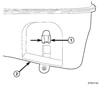
5. If the reservoir is being replaced, remove the fluid level switch. Push together the retaining tabs (1) holding the brake fluid level switch in place in the brake fluid reservoir (2), then pull the brake fluid level switch out the opposite side of the reservoir.
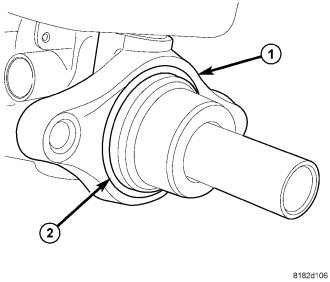
6. Remove the vacuum seal (2) from the master cylinder mounting flange (1).
ASSEMBLY
1. Install a NEW vacuum seal (2) on the master cylinder mounting flange (1) making sure the seal fits squarely in its groove.
2. If the reservoir is being replaced, align the brake fluid level switch with its mounting hole on the left side of the master cylinder brake fluid reservoir. Push the switch into the fluid reservoir until the switch retaining tabs (1) are expanded on the other side of the reservoir (2), locking it in place.
3. Lubricate the reservoir mounting area with fresh clean brake fluid. Place the reservoir (1) in position over the grommet seals in the master cylinder (2). Slide the reservoir into the grommet seals by firmly pressing down on the fluid reservoir. Once installed, make sure fluid reservoir is touching the top of both grommet seals.
4. Install the fluid reservoir mounting screw (3). Tighten the screw to 5.5 N·m (48 in. lbs.).
5. Thoroughly bleed the master cylinder before installing it. (Refer to 5 - BRAKES/HYDRAULIC/MECHANICAL/MASTER CYLINDER - STANDARD PROCEDURE)
6. Install the master cylinder. (Refer to 5 - BRAKES/HYDRAULIC/MECHANICAL/MASTER CYLINDER - INSTALLATION)