C1461-AWD SWITCH CIRCUIT LOW
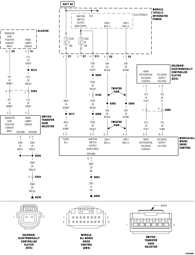
For a complete wiring diagram Refer to Section 8W
- When Monitored:
With the ignition on and no system undervoltage or overvoltage or supply voltage low conditions present.
- Set Condition:
The Transfer Case Selector Switch Voltage is below a specified value for a calibrated amount of time.
| Possible Causes |
| (K77) TRANSFER CASE POSITION SENSOR INPUT CIRCUIT SHORTED TO GROUND |
| (K77) TRANSFER CASE POSITION SENSOR INPUT CIRCUIT OPEN |
| (Z940) GROUND CIRCUIT OPEN |
| TRANSFER CASE SELECTOR SWITCH |
| INSTRUMENT CLUSTER (CCN) |
Diagnostic Test
1. TRANSFER CASE POSITION SENSOR SWITCH VOLTAGE LESS THAN 0.2 VOLTSIgnition on, engine not running.
NOTE: Repair any system undervoltage or overvoltage DTCs that are set in this module before proceeding.
With the scan tool, read the Transfer Case Position Sensor Switch voltage in the CCN.
Is the voltage less than 0.2 volts?
Yes
- Go To 2
No
- Go To 6
2. TRANSFER CASE SELECTOR SWITCH
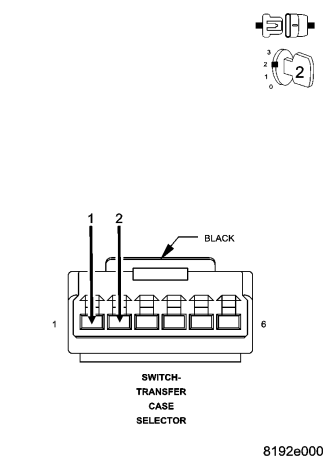
Turn the ignition off to the lock position
Disconnect the Transfer Case Selector Switch harness connector.
Connect a jumper wire between the (K77) Transfer Case Position Sensor Input circuit and the (Z940) Ground circuit in the Transfer Case Selector Switch harness connector.
Ignition on, engine not running.
With the scan tool, read the Transfer Case Position Sensor Switch voltage.
The switch voltage should be approximately 5.0 volts.
Does the voltage display as described?
Yes
- Replace the Transfer Case Selector Switch.
- Perform BODY VERIFICATION TEST - VER 1. (Refer to 8 - ELECTRICAL/ELECTRONIC CONTROL MODULES - STANDARD PROCEDURE)
No
- Go To 3
3. (K77) TRANSFER CASE POSITION SENSOR INPUT CIRCUIT SHORTED TO GROUND
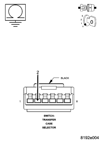
Turn the ignition off to the lock position
Disconnect the CCN C3 harness connector.
Measure the resistance between ground and the (K77) Transfer Case Position Sensor Input circuit.
Is the resistance less than 5.0 ohms?
Yes
- Repair the (K77) Transfer Case Position Sensor Input circuit for a short to ground.
- Perform BODY VERIFICATION TEST - VER 1. (Refer to 8 - ELECTRICAL/ELECTRONIC CONTROL MODULES - STANDARD PROCEDURE)
No
- Go To 4
4. (K77) TRANSFER CASE POSITION SENSOR INPUT CIRCUIT OPEN
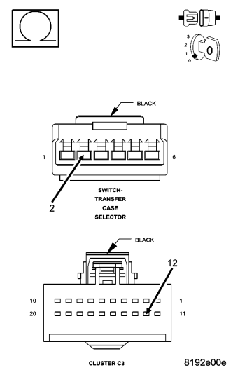
Measure the resistance of the (K77) Transfer Case Position Sensor Input circuit between the Transfer Case Selector Switch harness connector and the CCN C3 harness connector.
Is the resistance greater than 5.0 ohms?
Yes
- Repair the (K77) Transfer Case Position Sensor Input circuit for an open.
- Perform BODY VERIFICATION TEST - VER 1. (Refer to 8 - ELECTRICAL/ELECTRONIC CONTROL MODULES - STANDARD PROCEDURE)
No
- Go To 5
5. (Z940) GROUND CIRCUIT OPEN
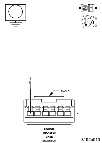
Measure the resistance of the (Z940) Ground circuit between the Transfer Case Selector Switch harness connector and the CCN C3 harness connector.
Is the resistance above 5.0 ohms?
Yes
- Repair the (Z940) Ground circuit for an open.
- Perform BODY VERIFICATION TEST - VER 1. (Refer to 8 - ELECTRICAL/ELECTRONIC CONTROL MODULES - STANDARD PROCEDURE)
No
- Replace the CCN in accordance with the Service Information.
- Perform BODY VERIFICATION TEST - VER 1. (Refer to 8 - ELECTRICAL/ELECTRONIC CONTROL MODULES - STANDARD PROCEDURE)
6. INTERMITTENT WIRING AND CONNECTORS
The conditions necessary to set this DTC are not present at this time.
Using the wiring diagram/schematic as a guide, inspect the wiring and connectors.
While monitoring the scan tool data relative to this circuit, wiggle test the wiring and connectors.
Look for the data to change or for the DTC to reset during the wiggle test.
While monitoring the scan tool data relative to this circuit, move the selector switch to each position several times.
Look for the data to change other than as expected or for the DTC to reset.
Were any problems found?
Yes
- Repair as necessary.
- Perform BODY VERIFICATION TEST - VER 1. (Refer to 8 - ELECTRICAL/ELECTRONIC CONTROL MODULES - STANDARD PROCEDURE)
No
- Test complete.