COLUMN
DESCRIPTION
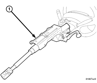
This vehicle is equipped with a tilt type steering column (1). The steering column is designed to be serviced only as complete assembly if an internal component is found to be defective. The shaft, bearings and intermediate shaft are all serviced with the column.
The serviceable components on the steering column assembly are:
- Clockspring (Integral part of Steering Column Control Module (SCCM))
- Driver Airbag
- Ignition Switch
- Key Cylinder
- Lock Cylinder Housing
- Multi-Function Switches (left and right)
- Tilt Lever
- Shrouds
- Steering Wheel
These components can be serviced without removal of the steering column from the vehicle. Refer to the appropriate section for servicing these components separately.
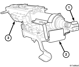
A special steering column is used in some Export areas meeting Thatcham security requirements. This steering column (3) is much the same as the standard steering column except for the addition of a tamper-proof shield (2) around the lock cylinder housing and an antitheft cup (1) surrounding the key cylinder. The tamper-proof shield disallows service of the lock cylinder housing. The antitheft cup can be removed allowing access to the key cylinder for service purposes.
The Thatcham steering column also features a ratcheting slip collar internal to the column assembly. This collar is not serviceable.
DISASSEMBLY
STEERING COLUMN CONTROL MODULE
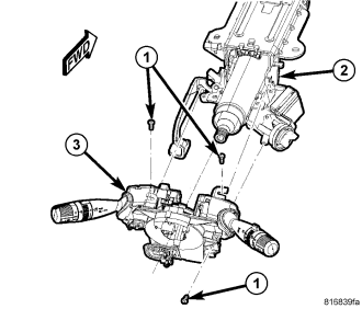
1. Remove the screws (1) attaching the Steering Column Control Module (SCCM) (with switch stalks) (3) to the steering column (2).
2. Slide the SCCM (with switch stalks) (3) off the steering column (2).
SKREEM/WCM (IF EQUIPPED)
NOTE: SCCM previously removed.
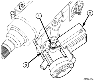
1. Remove the screw (1) fastening the SKREEM/WCM (2) to the lock cylinder housing (3).
2. Unhook the SKREEM/WCM (2) retainer fingers from the lock cylinder housing (3) and remove it from the housing.
KEY CYLINDER
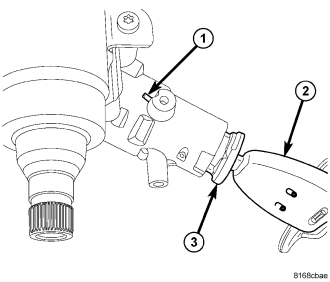
NOTE: SCCM and SKREEM/WCM previously removed.
1. Insert the key (2) and turn the key cylinder (3) to the RUN position.
2. Insert an appropriate tool into the slot (1) formed into the lock cylinder housing depressing the key cylinder retaining tab.
3. Pull the key cylinder and key straight out of the lock cylinder housing as one unit.
LOCK CYLINDER HOUSING
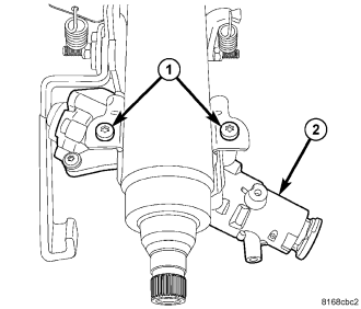
NOTE: SCCM previously removed.
1. Using Tamper-Proof Torx® Plus (five point) 30 bit, remove the two screws (1) fastening the lock cylinder housing (2) to the column.
2. Remove the lock cylinder housing from the steering column.
IGNITION SWITCH
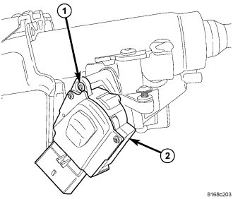
NOTE: Lock cylinder housing removed from column.
1. Remove the ignition switch (2) mounting screw (1).
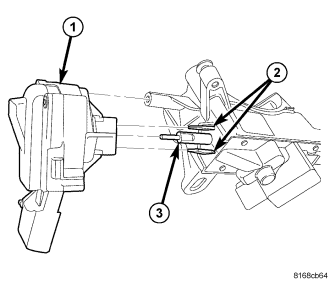
2. Pull the switch (1) straight out and off the retaining tabs (2) located on the lock cylinder housing.
INSPECTION
Replace the steering column if the driver airbag has deployed, regardless of the extent of damage to the vehicle.
ASSEMBLY
NOTE: Assemble the column components in the order shown to ensure proper installation of all components.
IGNITION SWITCH
1. Ensure the ignition switch is in the RUN position and the actuator shaft in the lock housing is in the RUN position.
2. Align the ignition switch with the pin (3), actuator shaft and retaining tabs (2) located on the lock cylinder housing. Carefully install the switch snapping it into place over the retaining tabs.
3. Install the ignition switch (2) mounting screw (1). Tighten the screw to 2 N·m (18 in. lbs.).
LOCK CYLINDER HOUSING
1. Position the lock cylinder housing in the RUN position.
2. Align the lock cylinder housing (2) with the steering column.
3. Install the two screws (1) fastening the lock cylinder housing (2) to the column. Tighten the screws to 15 N·m (130 in. lbs.).
KEY CYLINDER
1. Place the actuator in the lock cylinder housing to the RUN position (if not already there).
2. Insert the key into the key cylinder and turn the key cylinder to the RUN position.
3. Align the retaining tab on the key cylinder with the slot in the top of the lock cylinder housing.
4. Slide the key cylinder into the lock cylinder housing until the key cylinder retaining tab locks the cylinder into place.
5. Rotate the key back and forth, then remove and reinstall it, making sure the key cylinder and lock cylinder housing operate properly.
SKREEM/WCM (IF EQUIPPED)
1. Slide the ring of the SKREEM/WCM (2) over the lock cylinder housing (3) and engage the retainer fingers in the recesses formed on the lock cylinder housing.
2. Install the screw (1) fastening the SKREEM/WCM (2) to the lock cylinder housing (3). Tighten the screw to 2.5 N·m (22 in. lbs.).
STEERING COLUMN CONTROL MODULE
1. Slide the Steering Column Control Module (SCCM) (with switch stalks) (3) onto the steering column (2).
2. Install the screws (1) attaching the SCCM (with switch stalks) (3) to the steering column (2). Tighten the screws to 3 N·m (25 in. lbs.).