*NO RESPONSE FROM TIPM (TOTALLY INTEGRATED POWER MODULE)
For a complete wiring diagram Refer to Section 8W.
| Possible Causes |
| DIRECT BATTERY FEED CIRCUIT OPEN |
| GROUND CIRCUITS OPEN |
| DIAGNOSTIC CAN C CIRCUITS OPEN |
| DIAGNOSTIC CAN C CIRCUITS SHORTED TO GROUND |
| DIAGNOSTIC CAN C CIRCUITS SHORTED TOGETHER |
| TOTALLY INTEGRATED POWER MODULE |
Diagnostic Test
1. TEST FOR INTERMITTENT CONDITIONNOTE: Check for any TSB(s) related to the condition. If a TSB applies, perform the procedure outlined in the TSB before continuing.
NOTE: Ensure the IOD fuse is installed and battery voltage is between 10.0 and 16.0 volts.
NOTE: Ensure the scan tool is updated to the latest software.
NOTE: If the scan tool displays any error messages involving the Diagnostic CAN C circuits, diagnose and repair the errors before proceeding. Refer to the Table of Contents.
NOTE: A loss of communication with the TIPM can cause the ECU View button on the scan tool to be inoperative (not highlighted).
Turn the ignition on.
With the scan tool, attempt to select ECU View.
Can the scan tool communicate with the TIPM?
Yes
- The no response condition is not present at this time. Using the wiring diagram/schematic as a guide, inspect the wiring for chafed, pierced, pinched, and partially broken wires and the wiring harness connectors for broken, bent, pushed out, and corroded terminals.
No
- Go To 2
2. DIRECT BATTERY FEED CIRCUIT OPEN AT TIPM
Disconnect the scan tool from the DLC.
Using a 12-volt test light connected to ground, and using the wiring diagram as a guide, check the direct battery feed circuit at the TIPM.
Does the test light illuminate brightly?
Yes
- Go To 3
No
- Repair the direct battery feed circuit for an open.
- Perform the BODY VERIFICATION TEST - VER 1. (Refer to 8 - ELECTRICAL/ELECTRONIC CONTROL MODULES - STANDARD PROCEDURE)
3. GROUND CIRCUITS OPEN AT TIPM
Turn the ignition off.
Using a 12-volt test light connected to 12-volts, and using the wiring diagram as a guide, check all ground circuits at the TIPM.
Does the test light illuminate brightly on each circuit?
Yes
- Go To 4
No
- Repair the ground circuit that did not light the test light for an open.
- Perform the BODY VERIFICATION TEST - VER 1. (Refer to 8 - ELECTRICAL/ELECTRONIC CONTROL MODULES - STANDARD PROCEDURE)
4. CHECK FOR (D72) DIAGNOSTIC CAN C (+) CIRCUIT OPEN AT DLC
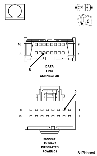
Disconnect the TIPM C3 harness connector.
Measure the resistance on the (D72) Diagnostic CAN C (+) circuit between the TIPM C3 harness connector and the DLC.
Is the resistance above 10.0 ohms?
Yes
- Repair the (D72) Diagnostic CAN C (+) circuit for an open.
- Perform the BODY VERIFICATION TEST - VER 1. (Refer to 8 - ELECTRICAL/ELECTRONIC CONTROL MODULES - STANDARD PROCEDURE)
No
- Go To 5
5. CHECK FOR (D71) DIAGNOSTIC CAN C (-) CIRCUIT OPEN AT DLC
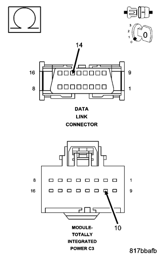
Measure the resistance on the (D71) Diagnostic CAN C (-) circuit between the TIPM C3 harness connector and the DLC.
Is the resistance above 10.0 ohms?
Yes
- Repair the (D71) Diagnostic CAN C (-) circuit for an open.
- Perform the BODY VERIFICATION TEST - VER 1. (Refer to 8 - ELECTRICAL/ELECTRONIC CONTROL MODULES - STANDARD PROCEDURE)
No
- Go To 6
6. CHECK FOR (D72) DIAGNOSTIC CAN C (+) CIRCUIT SHORTED TO GROUND
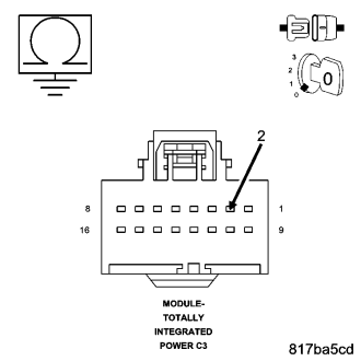
Measure the resistance between ground and the (D72) Diagnostic CAN C (+) circuit at the TIPM C3 harness connector.
Is the resistance below 100.0 ohms?
Yes
- Repair the (D72) Diagnostic CAN C (+) circuit for a short to ground.
- Perform the BODY VERIFICATION TEST - VER 1. (Refer to 8 - ELECTRICAL/ELECTRONIC CONTROL MODULES - STANDARD PROCEDURE)
No
- Go To 7
7. CHECK FOR (D71) DIAGNOSTIC CAN C (-) CIRCUIT SHORTED TO GROUND
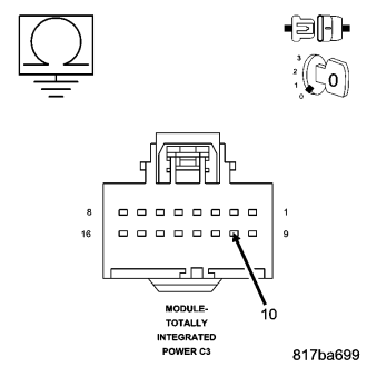
Measure the resistance between ground and the (D71) Diagnostic CAN C (-) circuit at the TIPM C3 harness connector.
Is the resistance below 100.0 ohms?
Yes
- Repair the (D71) Diagnostic CAN C (-) circuit for a short to ground.
- Perform the BODY VERIFICATION TEST - VER 1. (Refer to 8 - ELECTRICAL/ELECTRONIC CONTROL MODULES - STANDARD PROCEDURE)
No
- Go To 8
8. CHECK FOR DIAGNOSTIC CAN C CIRCUITS SHORTED TOGETHER
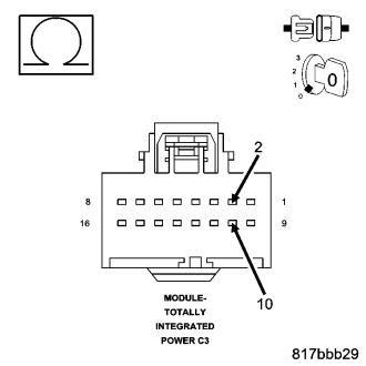
Measure the resistance between the (D72) Diagnostic CAN C (+) circuit and the (D71) Diagnostic CAN C (-) circuit at the TIPM C3 harness connector.
Is the resistance below 100.0 ohms?
Yes
- Repair the (D72) Diagnostic CAN C (+) circuit for a short to the (D71) Diagnostic CAN C (-) circuit.
- Perform the BODY VERIFICATION TEST – VER 1. (Refer to 8 - ELECTRICAL/ELECTRONIC CONTROL MODULES - STANDARD PROCEDURE).
No
- Replace the Totally Integrated Power Module in accordance with the service information.
- Perform the BODY VERIFICATION TEST – VER 1. (Refer to 8 - ELECTRICAL/ELECTRONIC CONTROL MODULES - STANDARD PROCEDURE).