STANDARD PROCEDURE
- REPAIR OF DAMAGED OR WORN THREADS
- HYDROSTATIC LOCKED ENGINE
- FORM-IN-PLACE GASKETS AND SEALERS
- ENGINE GASKET SURFACE PREPARATION
- CYLINDER HEAD CORE PLUGS
- MEASURING BEARING CLEARANCE USING PLASTIGAGE
REPAIR OF DAMAGED OR WORN THREADS
Damaged or worn threads (excluding spark plug and camshaft bearing cap attaching threads) can be repaired. Essentially, this repair consists of drilling out worn or damaged threads, tapping the hole with a special Heli-Coil Tap, (or equivalent) and installing an insert into the tapped hole. This brings the hole back to its original thread size.
CAUTION: Be sure that the tapped holes maintain the original center line.
Heli-Coil tools and inserts are readily available from automotive parts jobbers.
HYDROSTATIC LOCKED ENGINE
When an engine is suspected to be hydrostatically locked, regardless of what caused the problem, the following steps should be used.
CAUTION: DO NOT use starter motor to rotate the engine, severe damage may occur.
1. Inspect air cleaner, induction system and intake manifold to insure system is dry and clear of foreign material.
2. Remove negative battery cable.
3. Place a shop towel around the spark plugs when removing them from the engine. This will catch any fluid that may possibly be in the cylinder under pressure.
4. With all spark plugs removed, rotate engine crankshaft using a breaker bar and socket.
5. Identify the fluid in the cylinder(s) (i.e., coolant, fuel, oil or other).
6. Make sure all fluid has been removed from the cylinders. Inspect engine for damage (i.e., connecting rods, pistons, valves, etc.)
7. Repair engine or components as necessary to prevent this problem from re-occurring.
CAUTION: Squirt approximately one teaspoon of oil into the cylinders, rotate engine to lubricate the cylinder walls to prevent damage on restart.
8. Install new spark plugs.
9. Drain engine oil and remove oil filter.
10. Install a new oil filter.
11. Fill engine with specified amount of approved oil.
12. Connect negative battery cable.
13. Start engine and check for any leaks.
FORM-IN-PLACE GASKETS AND SEALERS
NOTE: All of the sealants mentioned below are not used on every engine, they are listed as general reference guide. See service information for specific sealer usage.
There are numerous places where form-in-place gaskets are used on the engine. Care must be taken when applying form-in-place gaskets to assure obtaining the desired results. Do not use form-in-place gasket material unless specified. Bead size, continuity, and location are of great importance. Too thin a bead can result in leakage while too much can result in spill-over which can break off and obstruct fluid feed lines. A continuous bead of the proper width is essential to obtain a leak-free gasket. All sealing surfaces that use form-in-place gaskets and sealers must free of grease or oil. Surfaces should be cleaned with Mopar® brake parts cleaner prior to sealer application. After the sealer is applied, the parts should be assembled in no more than 10 minutes.
There are numerous types of form-in-place gasket materials that are used in the engine area. Mopar® Engine RTV GEN II, Mopar® ATF-RTV, and Mopar® Gasket Maker gasket materials, each have different properties and can not be used in place of the other.
MOPAR® ENGINE RTV GEN II is used to seal components exposed to engine oil. This material is a specially designed black silicone rubber RTV that retains adhesion and sealing properties when exposed to engine oil. Moisture in the air causes the material to cure. This material is available in three ounce tubes and has a shelf life of one year. After one year this material will not properly cure. Always inspect the package for the expiration date before use.
MOPAR® ATF RTV is a specifically designed black silicone rubber RTV that retains adhesion and sealing properties to seal components exposed to automatic transmission fluid, engine coolants, and moisture. This material is available in three ounce tubes and has a shelf life of one year. After one year this material will not properly cure. Always inspect the package for the expiration date before use.
MOPAR® GASKET MAKER is an anaerobic type gasket material. The material cures in the absence of air when squeezed between two metallic surfaces. It will not cure if left in the uncovered tube. The anaerobic material is for use between two machined surfaces. Do not use on flexible metal flanges.
MOPAR® BED PLATE SEALANT is a unique (green-in-color) anaerobic type gasket material that is specially made to seal the area between the bed plate and cylinder block without disturbing the bearing clearance or alignment of these components. The material cures slowly in the absence of air when torqued between two metallic surfaces, and will rapidly cure when heat is applied.
MOPAR® GASKET SEALANT is a slow drying, permanently soft sealer. This material is recommended for sealing threaded fittings and gaskets against leakage of oil and coolant. Can be used on threaded and machined parts under all temperatures. This material also will prevent corrosion. Mopar® Gasket Sealant is available in a 13 oz. aerosol can or 4oz./16 oz. can w/applicator.
SEALER APPLICATION
Mopar® Gasket Maker material should be applied sparingly 1 mm (0.040 in.) diameter or less of sealant to one gasket surface. Be certain the material surrounds each mounting hole. Excess material can easily be wiped off. Components should be torqued in place within 15 minutes. The use of a locating dowel is recommended during assembly to prevent smearing material off the location.
Mopar® Engine RTV GEN II or ATF RTV gasket material should be applied in a continuous bead approximately 3 mm (0.120 in.) in diameter. All mounting holes must be circled. For corner sealing and “T” joint locations, a 3.17 or 6.35 mm (1/8 or 1/4 in.) drop is placed in the center of the gasket contact area. Uncured sealant may be removed with a shop towel. Components should be torqued in place while the sealant is still wet to the touch (within 10 minutes). The usage of a locating dowel is recommended during assembly to prevent smearing material off the location.
Mopar® Gasket Sealant in an aerosol can should be applied using a thin, even coat sprayed completely over both surfaces to be joined, and both sides of a gasket. Then proceed with assembly. Material in a can w/applicator can be brushed on evenly over the sealing surfaces.
ENGINE GASKET SURFACE PREPARATION
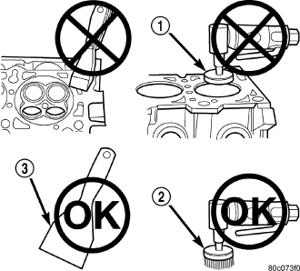
To ensure engine gasket sealing, proper surface preparation must be performed, especially with the use of aluminum engine components and multi-layer steel cylinder head gaskets.
Never use the following to clean gasket surfaces:
- Metal scraper.
- Abrasive pad or paper to clean cylinder block and head.
- High speed power tool with an abrasive pad or a wire brush (1).
NOTE: Multi-Layer Steel (MLS) head gaskets require a scratch free sealing surface.
Only use the following for cleaning gasket surfaces:
- Solvent or a commercially available gasket remover
- Plastic or wood scraper (3).
- Drill motor with 3M Roloc™ Bristle Disc (white or yellow) (2).
CAUTION: Excessive pressure or high RPM (beyond the recommended speed), can damage the sealing surfaces. The mild (white, 120 grit) bristle disc is recommended. If necessary, the medium (yellow, 80 grit) bristle disc may be used on cast iron surfaces with care.
Sealing surfaces must be free of grease or oil residue. Clean surfaces with Mopar® brake parts cleaner (or equivalent).
CYLINDER HEAD CORE PLUGS
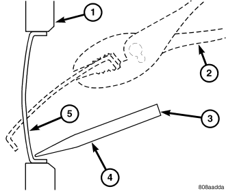
Using a blunt tool (3) such as a drift and a hammer, strike the bottom edge of the cup plug (5). With the cup plug rotated, grasp firmly with pliers or other suitable tool (2) and remove plug (5).
CAUTION: Do not drive cup plug into the casting as restricted cooling can result and cause serious engine problems.
Thoroughly clean inside of cup plug hole in cylinder head. Be sure to remove old sealer. Lightly coat inside of cup plug hole with Mopar® Stud and Bearing Mount. Make certain the new plug is cleaned of all oil or grease. Using proper drive plug, drive plug into hole so that the sharp edge of the plug is at least 0.5 mm (0.020 in.) inside the lead-in chamfer.
It is not necessary to wait for curing of the sealant. The cooling system can be refilled and the vehicle placed in service immediately.
MEASURING BEARING CLEARANCE USING PLASTIGAGE
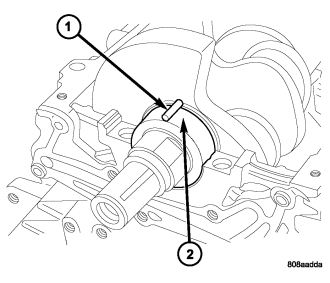
Engine crankshaft bearing clearances can be determined by use of Plastigage or equivalent. The following is the recommended procedure for the use of Plastigage:
1. Remove oil film from surface to be checked. Plastigage is soluble in oil.
2. Place a piece of Plastigage (1) across the entire width of the journal. (In addition, suspected areas can be checked by placing the Plastigage in the suspected area). Torque the bearing cap bolts of the bearing being checked to the proper specifications.
3. Remove the bearing cap and compare the width of the flattened Plastigage with the scale provided on the package. Locate the band closest to the same width. This band shows the amount of clearance. Differences in readings between the ends indicate the amount of taper present. Record all readings taken. Compare clearance measurements to specs found in engine specifications (Refer to 9 - ENGINE - SPECIFICATIONS). Plastigage generally is accompanied by two scales. One scale is in inches, the other is a metric scale.
NOTE: Plastigage is available in a variety of clearance ranges. Use the most appropriate range for the specifications you are checking.
4. Install the proper crankshaft bearings to achieve the specified bearing clearances.