*CHECKING THE ECM POWER AND GROUND CIRCUITS
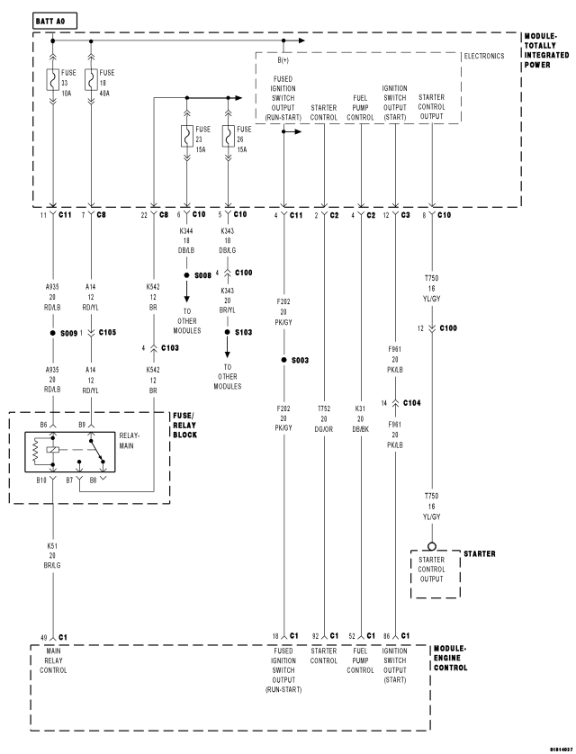
| Possible Causes |
| MAIN RELAY CONTROL CIRCUIT OPEN |
| MAIN RELAY OUTPUT CIRCUIT(S) OPEN |
| CHECKING THE MAIN RELAY SYSTEM |
| ECM GROUND CIRCUIT(S) OPEN |
| FUSED MAIN RELAY BATTERY SUPPLY CIRCUIT OPEN |
| FUSED IGNITION SWITCH (START) OUTPUT CIRCUIT OPEN |
| FUSED IGNITION SWITCH (START/RUN) OUTPUT CIRCUIT OPEN |
| SUBSTITUTE MAIN RELAY |
| MAIN RELAY CONTROL CIRCUIT SHORTED TO VOLTAGE |
Diagnostic Test
1. ECM GROUND CIRCUIT(S) OPENNOTE: Before checking the ECM Power and Grounds, check the Totally Integrated Power Module (TIPM) for DTC's. Repair all TIPM ignition switch or power supply related DTC's before continuing with this test.
Turn the ignition off.
Disconnect the ECM harness connectors.
Using a 12-volt test light connected to 12-volts, check each of the ECM ground circuits in ECM harness connector C1 cavities 1, 2 and 4.
Did the test light illuminate for each cavity?
Yes
- Go To2
No
- Repair the ECM Ground circuit(s) for an open.
- Perform the ECM Verification Test Ver. 1. (Refer to 9 - ENGINE - DIAGNOSIS AND TESTING)
2. FUSED IGNITION SWITCH START OUTPUT CIRCUIT OPEN
Turn the ignition to the Start position.
Using a 12-volt test light connected to ground, check the Fused Ignition Switch Start Output circuit in ECM harness connector C1 cavity 86.
Is the test light on?
Yes
- Go To3
No
- Repair the Fused Ignition Switch Start Output circuit for an open.
- Perform the ECM Verification Test Ver. 1. (Refer to 9 - ENGINE - DIAGNOSIS AND TESTING)
3. FUSED IGNITION SWITCH START/RUN OUTPUT CIRCUIT OPEN
Turn the ignition to the Start position.
Using a 12-volt test light connected to ground, check the Fused Ignition Switch Start/Run Output circuit in ECM harness connector C1 cavity 18.
Turn the ignition to the Run position.
Using a 12-volt test light connected to ground, check the Fused Ignition Switch Start/Run Output circuit in ECM harness connector C1 cavity 18.
Is the test light on for both ignition switch positions?
Yes
- Go To4
No
- Repair the Fused Ignition Switch Start/Run Output circuit for an open.
- Perform the ECM Verification Test Ver. 1. (Refer to 9 - ENGINE - DIAGNOSIS AND TESTING)
4. CHECKING THE MAIN RELAY SYSTEM
Turn the ignition off.
Connect a jumper wire between ground and the Main Relay Control circuit in ECM C1 harness connector cavity 49.
Turn the ignition on.
Using a 12-volt test light connected to ground, check the Fused Main Relay Output circuits at the ECM C1 harness connector cavities 3, 5 and 6.
Does the test light illuminate brightly for each circuit?
Yes
- Test Complete.
No
- Go To5
5. FUSED MAIN RELAY BATTERY SUPPLY CIRCUIT OPEN
Turn the ignition off.
Remove the Main Relay.
Using a 12-volt test light connected to ground, check both Fused Main Relay Battery Supply circuits in Main Relay connector.
Is the test light on?
Yes
- Go To6
No
- Repair the Fused Main Relay Battery Supply circuit(s) for an open.
- Perform the ECM Verification Test Ver. 1. (Refer to 9 - ENGINE - DIAGNOSIS AND TESTING)
6. MAIN RELAY OUTPUT CIRCUIT OPEN
Connect a jumper wire between cavity B7 and cavity B9 in the Main Relay connector.
Using a 12-volt test light connected to ground, check the Main Relay Output circuit in ECM harness connector C1 cavities 3, 5 and 6.
Did the test light illuminate for each circuit?
Yes
- Go To7
No
- Repair the Main Relay Output circuit(s) for an open.
- Perform the ECM Verification Test Ver. 1. (Refer to 9 - ENGINE - DIAGNOSIS AND TESTING)
7. MAIN RELAY
Turn the ignition off.
Install a known good relay in place of the Main Relay.
Connect a jumper wire between ground and the Main Relay Control circuit in ECM C1 harness connector cavity 49.
Turn the ignition on.
Using a 12-volt test light connected to ground, check the Fused Main Relay Output circuits at the ECM C1 harness connector cavities 3, 5 and 6.
Did the test light illuminate brightly for each circuit?
Yes
- Replace the Main Relay.
- Perform the ECM Verification Test Ver. 1. (Refer to 9 - ENGINE - DIAGNOSIS AND TESTING)
No
- Repair the Main Relay Control circuit for an open or short to voltage.
- Perform the ECM Verification Test Ver. 1. (Refer to 9 - ENGINE - DIAGNOSIS AND TESTING)