*ENGINE WILL NOT CRANK
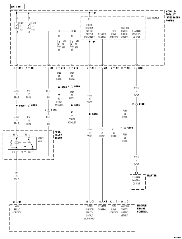
For a complete wiring diagram Refer to Section 8W
| Possible Causes |
| BATTERY CABLES |
| LOW BATTERY/POOR BATTERY CONNECTION |
| CLUTCH INTERLOCK SWITCH INPUT |
| MECHANICAL PROBLEM |
| SKIM CODES PRESENT |
| STARTER MOTOR |
| TOTALLY INTEGRATED POWER MODULE |
| (T750) STARTER CONTROL OUTPUT CIRCUIT SHORT TO GROUND |
| (T750) STARTER CONTROL OUTPUT CIRCUIT OPEN |
Diagnostic Test
1. BATTERY CABLESNOTE: Ensure there are no Active DTC's in the ECM or TIPM. If the ECM or TIPM have Active DTC's, repair these DTC's before continuing with No Crank diagnosis.
Turn the ignition off.
NOTE: The battery must be fully charged before diagnosing a no crank condition.
Inspect the battery cables for corrosion, looseness or other problems.
Is there evidence of problems?
Yes
- Repair as necessary.
- Perform the ECM Verification Test Ver. 1 (Refer to 9 - ENGINE - DIAGNOSIS AND TESTING).
No
- Go To 2
2. ECM POWER AND GROUND CIRCUITS
Refer to CHECKING THE ECM POWER AND GROUNDS to check for proper ignition, battery and ground supply to the ECM.
Are the Ignition, Battery and Ground supply circuits functioning properly at the ECM?
Yes
- Go To 3
- Perform the ECM Verification Test Ver. 1 (Refer to 9 - ENGINE - DIAGNOSIS AND TESTING).
No
- Repair as necessary.
3. SKIM CODES PRESENT
Turn the ignition on.
With the scan tool, read the SKIM DTCs.
Does the scan tool display any SKIM DTCs?
Yes
- Refer to symptom list for problems related to SKIM.
- Perform the ECM Verification Test Ver. 1 (Refer to 9 - ENGINE - DIAGNOSIS AND TESTING).
No
- Go To 4
4. CHECKING STARTER OPERATION
NOTE: The Starter Motor Fuse in the TIPM must not be open for this test to be valid. Check the condition of the Starter Motor Fuse in the TIPM. If the fuse is open, replace and attempt to crank the engine.
Turn the ignition off.
Disconnect the (T750) Starter Control Output circuit at the Starter Motor.
With a 12–volt test light connected to ground, probe the (T750) Starter Control Output circuit.
Fully depress the clutch pedal.
While observing the test light, turn the ignition switch to the Crank/Start position.
Is the test light illuminated brightly?
Yes
- Go To 5
No
- Go To 6
5. MECHANICAL PROBLEM
Turn the ignition off.
Attempt to manually rotate the crankshaft 360°.
Is the crankshaft able to rotate 360°?
Yes
- Replace the Starter Motor.
- Perform the ECM Verification Test Ver. 1 (Refer to 9 - ENGINE - DIAGNOSIS AND TESTING).
No
- Repair the engine mechanical problem.
- Perform the ECM Verification Test Ver. 1 (Refer to 9 - ENGINE - DIAGNOSIS AND TESTING).
6. VERIFY CLUTCH SWITCH INPUTS
Turn the ignition on.
With the scan tool, read the Clutch Upstop Switch and Clutch Interlock Switch inputs while fully depressing and releasing the clutch pedal.
Does the input for both switched change state while fully depressing and releasing the clutch pedal?
Yes
- Go To 7
No
- Refer to the Service Information related to the Clutch Switch. Repair or replace Clutch Switch or Clutch Switch circuitry as necessary to correct Clutch Switch input to the ECM.
- Perform the ECM Verification Test Ver. 1 (Refer to 9 - ENGINE - DIAGNOSIS AND TESTING).
7. (T750) STARTER CONTROL OUTPUT CIRCUIT OPEN
Turn the ignition off.
Disconnect the TIPM C8 harness connector.
Connect the (T750) Starter Control Output wire (at the Starter) to ground.
Using a 12-volt test light connected to 12-volts, check the (T750) Starter Relay Output circuit at the TIPM C8 harness connector.
Does the test light illuminate brightly?
Yes
- Go To 8
No
- Repair the (T750) Starter Relay Output circuit for an open.
- Perform the ECM Verification Test Ver. 1 (Refer to 9 - ENGINE - DIAGNOSIS AND TESTING).
8. (T750) STARTER CONTROL OUTPUT CIRCUIT SHORT TO GROUND
Measure the resistance between ground and the (T750) Starter Control Output circuit.
Is the resistance above 1000 ohms?
Yes
- Go To 9
No
- Repair the (T750) Starter Control Output circuit for a short to ground.
- Perform the ECM Verification Test Ver. 1 (Refer to 9 - ENGINE - DIAGNOSIS AND TESTING).
9. CHECK WIRING, CONNECTORS AND TERMINALS
Turn the ignition off.
Check the wiring, connectors and terminals associated with the Starter Relay, Main Relay and Clutch Switch circuits. Check for poor terminal contact, corrosion, spread terminals, improper connections or other problems that could cause an intermittent condition.
Were any problems found?
Yes
- Repair or replace wiring, connector or terminals as necessary.
- Perform the ECM Verification Test Ver. 1 (Refer to 9 - ENGINE - DIAGNOSIS AND TESTING).
No
- Replace the TIPM in accordance with the Service Information.
- Perform the ECM Verification Test Ver. 1 (Refer to 9 - ENGINE - DIAGNOSIS AND TESTING).